

With help from the Tasmota forums and my Italian friend Antonio, I’ve learned some very useful stuff to share, in the last couple of days.

Automatic router Re-Booter using Tasmota and Sonoff BASIC or Similar
I have a 5G router which then feeds a normal router (we have no fibre option where we live but a good 5G signal). The 5G router is, say, 95% reliable… the main router higher reliability – but from time to time, usually when I’m away from home – something goes wrong and I can no longer access stuff at home. I WAS getting the odd mains breaker issue but it turned out that our 2-year-old hot water tank had an internal LEAK (very high calcium levels in the water) – I replaced the tank and I’m down to worst-case 6ma total house leakage. Problem solved.
For some time I’ve had Node-Red (on my 24-7 home control Raspberry Pi 4) pinging Google regularly – and if no response that would trigger a 5g router reboot via a Tasmota-driven Sonoff BASIC-type device – but clearly I was not getting everything right as while I was on holiday recently – I lost control of the house. My non-technical neighbour thankfully came over and checked – I had him power-cycle the mains – he did that but later assured me the breakers had been fine. It looks like the normal router providing DHCP had failed (that’s the end of Node-Red). The power cycle of course fixed all that.
Move forward over a year. I decided to start again – ultimately putting my new 5g router on a UPS-powered extension which meant I needed a way to power-cycle the router in the event of no Internet for whatever reason – hence controlled by a Tasmota device – I read somewhere about using a rule in Tasmota so that the device itself could do the Google checking (Tasmota can’t do complicated checking without special compilation which I’m not about to do). I now have a working Tasmota rule on the power controller to the 5g router – I’ll share it here. The main thing was to ensure that the power cycler could operate all on it’s own even when its router was not getting any Internet.
In the Tasmota CONSOLE of the Sonoff-Basic-type device feeding power to the 5g router – I entered this FIRST (all one one line – not separate lines – and no line numbers, just a space between each part)…
Rule1
ON system#boot do Var1 5 ENDON
ON Var1#State>1439 DO Var1 1439 ENDON
ON Time#Minute|%var1% DO backlog WebQuery http://google.com/ GET ENDON
ON WebQuery#Data$!Done DO backlog Mult1 3; TimedPower 15000,off ENDON
ON WebQuery#Data=Done DO Var1 5 ENDON
ON Time#Minute=165 DO TimedPower1 15000,off ENDON
i.e.
Rule1 ON system#boot do Var1 5 ENDON ON Var1#State>1439 DO Var1 1439 ENDON ON Time#Minute|%var1% DO backlog WebQuery http://google.com/ GET ENDON ON WebQuery#Data$!Done DO backlog Mult1 3; TimedPower 15000,off ENDON ON WebQuery#Data=Done DO Var1 5 ENDON ON Time#Minute=165 DO TimedPower1 15000,off ENDON
Then this line:
Rule1 1;
SO… on system boot – set variable 1 to 5. Don’t let it get to more than 1439 (minutes). Every var1 minutes do a webquery. If Google doesn’t respond, multiply var1 by 3 and turn the power off for 15 seconds. if the result IS ok, set var1 back to 5 (minutes in this case).
As well as checking for no connection, I thought it might be good to add in an auto power cycle at 02:45 every morning (165 minutes into the day) so that’s in there as well.. Note that the TIMEDPOWER command has variants like TIMEDPOWER1, TIMEDPOWER2 etc… I used TimedPower1 here as I’m using a Tasmota device with two outputs and I’m using the first output for cycling router power. I found that out by trial and error as I did not find the explanation on the Tasmota site of multiple output variations for this command too helpful)
I personally don’t find Tasmota rules to be the easiest thing in the world when only created rarely so let me try to explain what the above rule set does. Bearing in mind – we don’t want to wear out the relay on the controller by very frequent switching which could happen with a long outage – I need a Google check (can’t use PING as Tasmota standard builds don’t have that) starting at every 5 minutes and if the Internet connection fails it will then power-cycle the mains (10 seconds off – then back on) and if that doesn’t fix it, it will try again in 15 minutes and so on up to once every every 24 hours, resetting back to 5 minutes after any/every successful connection to Google.
And that just works…. I was recommended to use that rather than DELAY – and turning the router power off for 10 seconds then back on – just seemed about right to me. The rule starts with 5 minute intervals for Google web queries. If the query fails, the interval is multiplied by 3 for next time – and power is turned off for 10 seconds and back on. If the query succeeds, the interval between checks is set back to 5 minutes.
So, that LOOKS like a solution to the problem of not-entirely-100%-reliable connectivity but before leaving I’ll let you see my LATEST version…
For anyone interested, my hopefully FINAL rule set… once you get into it, these rules aren’t so hard after all.
So, Tasmota mains smartplug… and for the sake of it, a spare mains controller who’s indicator light will stay on for a while in the event of an Internet outage… all this assumes my Home Assistant or other local machine has an MQTT broker.
Rule1 ON system#boot do power1 1 ENDON ON Time#Minute|5 DO Backlog WebQuery http://google.com/ GET ENDON ON WebQuery#Data$!Done DO Backlog Publish homeassistant/internet_status offline; TimedPower 15000,off ENDON ON event#manualcycle DO TimedPower1 15000,off ENDON

Rule1 1
And second device
Subscribe NetStatus, homeassistant/internet_status

Rule1 ON Event#NetStatus=offline DO TimedPower1 300000,ON ENDON

Rule1 1
I’m also logging the offline message with a timestamp – in Home Assistant so I can look back on failures from anywhere, either on my PC in the office or away, using the mobile companion APP and my VPN.
In configuration.yaml I noted I have a template: section so I’ve just added to that…
  - trigger:
      - platform: mqtt
        topic: homeassistant/internet_status
        payload: "offline"
    sensor:
      - name: "LEO"
        state: "{{ now().strftime('%Y-%m-%d %H:%M:%S') }}"
        icon: mdi:wifi-cancel
and in HA I added a tile for my sensors page – a simple logbook card with the entity sensor.leo (leo for last ethernet outage).
Indeed, that simple operation of adding the sensor to Home Assistant ended up as an all-evening job using my new best friend – Perplexity – and as far as AI’s go in 2025, this is turning out to be a winner…. but as this article is not about Home Assistant OR AI as such – I’ll leave that for another day.
Update May 18 2025 – better idea
If you’ve followed this far, that only worked so well – indeed it caused my 5G router to reboot more often than necessary….. so I’m currently playing with another version of the rebooter…
Rule1
 ON system#boot do backlog var1 1; power1 1 ENDON
 ON Var1#State>5 DO Var1 5 ENDON
 ON Time#Minute|%var1% DO backlog WebQuery http://1.1.1.1/ GET ENDON
 ON WebQuery#Data$!Done DO backlog var1 2; Publish homeassistant/second_internet_status offline; timedpower 5000,off ENDON
 ON WebQuery#Data=Done DO backlog Var1 1; Publish homeassistant/second_internet_status online; ENDON
So – why didn’t I use PING? I certainly could have – but that involves a custom build of Tasmota – bang goes OTA updates, so I decided against it. Right now, on system boot, set a variable for time to 1 i.e. 1 minute – and turn the Tasmota smartplug ON. The second line is historic for now. Line 3 – every minute do a webquery to 1.1.1.1 (not Google – can’t use the IP and I wanted to avoid name servers). On line 4, we check the last webquery result – if “offline” is returned, set the variable to 2 minutes – so don’t do webquery for 2 minutes – giving router time to reboot, publish the message on MQTT and turn off the router power for 5 seconds. If the webqueryon the other hand returned “online”, ensure that timer is set back to one minute and publish the “online” MQTT message. I realised that with my earlier delays there was a good chance of missing an outage – so this is a compromise. It remains to be seen if 2 minutes is enough for router reboot and setup.


Giving speech Control to a Zigbee2MQTT-managed Zigbee Device
Separately, my friend Antonio and I had just finished getting the above to work when he came up with something I’d not thought of before:
So using Zigbee2MQTT with various Zigbee controllers is not usually ideal if you want voice control – and we were in the process of messing with Sonoff Basic-type controllers as above and he came out with “why not make use of unused GPIOS on a Sonoff-type controller (GPIOs which are not attached to anything) and use them as on-off devices -controllable by multi-pressing of the Sonoff-type device or by MQTT or Tasmota web interface or Alexa voice as normal, but instead of a simple switch, when using the control to switch the GPIO(s) which won’t do anything, use a rule to have that action send MQTT directly from the device to control another MQTT-compatible device, in this case a Zigbee2MQTT compatible device which normally doesn’t work with Alexa.”
Hence an on-off command to the non-functional GPIOs would end up having that device send an MQTT command to the Zigbee device sitting in the same network to control IT’S output. Remember that the Sonoff-lookalike is running on WiFi but given Zigbee2MQTT running in the same building (in my case on my main home control Raspberry Pi 4 via a cheap Sonoff Zigbee dongle attached to USB on the RPi) it becomes easy for the two networks to interact.
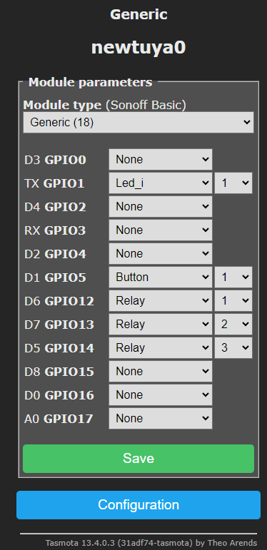
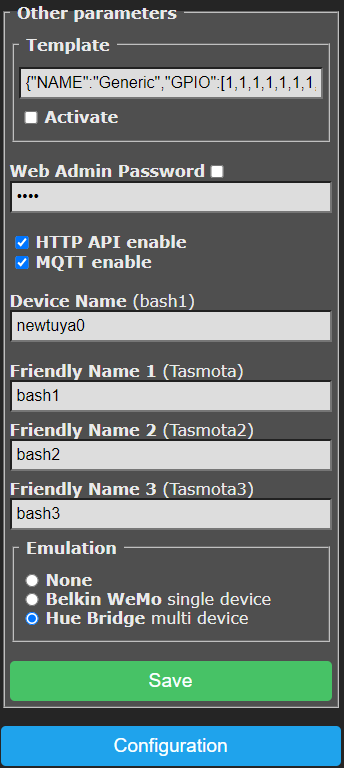
In this case – my Sonoff-basic-type device has power1, power2 and power3 – only the first one being actually connected to a relay – the other two connected to carefully-chosen GPIOs on that device – as it turns out this Sonoff-look-alike uses GPIO12 for the relay, GPIO5 for the button and GPIO1 for the LED – that leaves at least two useable GPIO outputs – maybe more – I chose GPIO13 and GPIO14. I called these outputs (under Tasmota Configuration – other) bash2 and bash3 (for no good reason) while ensuring the Tasmota setup was set to include emulation – Hue Bridge Multi-device.
The right Tasmota rules could make on-off and even brilliance/colour commands transfer to my Zigbee device (a lamp). So now I had a Zigbee device I could device I could control directly but also by ALEXA voice (sadly not Google) using a pair of outputs that don’t actually exist as well on the Sonoff-type device as the one that does – Tasmota rules and MQTT sorted that – I could now Alexa-control one of my cheap AliExpress Zigbee devices I’ve covered in a previous post … see code below…
rule1
on power2#state=1 do publish zigbee2mqtt/aliexpress-zigbee-3/set {"state":"on"} endon
on power2#state=0 do publish zigbee2mqtt/aliexpress-zigbee-3/set {"state":"off"} endon
i.e.
rule1 on power2#state=1 do publish zigbee2mqtt/aliexpress-zigbee-3/set {"state":"on"} endon on power2#state=0 do publish zigbee2mqtt/aliexpress-zigbee-3/set {"state":"off"} endon
rule1 1
The rule set above is somewhat simpler than the one further up in this article – the first 3 lines (in reality one line) detail a rule called rule1 – the last separate line ensures the rule is running (including after power cycle). That’s it. The name of the Zigbee device is the friendly name I chose to give it. aliexpress-zigbee-3. something like bathroom-light would likely be more useful but these devices are new and still on test. Renaming is a simple matter in the Zigbee2MQTT control interface (by default at port 9099 on my Raspberry Pi). This info is simply entered into the Tasmota console.
Of course, none of this helps Alexa’s utterly hopeless speech recognition – I could not tell you how many device names I’ve tried over the years with Alexa, only to be told that “this song is available in the Amazon music store” or similar.
I hope this gave readers some ideas. For more on Tasmota look here. For more on Zigbee2MQTT look here.
It works for me on Node Red V3.1.0 PI4 Bullseye but I’m doing a new build from scratch with “bookworm” and will try a Wemo Emulator install on that.
Ok guys lets keep this going.. I tried first on my Node-Red + Bullseye but 32-bit as I have a TON of stuff in there – not the latest 64-bit – the one I’ve updated for ages all the way from RPI2… and got the same failure message I got on my brand new RPI5 64 bit with NR 3 (almost nothing installed except Docker and Mosquitto and Zigbee2MQTT)… anyone any ideas why both would fail? I used the MANAGE PALETTE in NR in both cases.
about alexa and multiple tasmota enabled devices, you can even just use a whatever esp you have around, mapping each free gpio to a relay and just use for that, with hue emulation
Unless I am missing something.. why not use node-red-contrib-wemo-emulator
in node red to “alexa” talk to Zigbee2MQTT
because that requires nodered, while my solution is completely working with just tasmota and its rules, and of course mosquitto broker
Just for the sake of it I tried installing Node-Red-Wemo-Emulator on my RPI4 with up to date NR etc.
Failed to install: node-red-contrib-wemo-emulator
Install failed
Check the log for more information
So the solution we have here still stands.