
I just received this US/EU Plug 12/24 hour from Banggood (pre-assembled), complete with a US plug – but as that’s a separate USB charger it’s not that important – they do supply both EU and USA USB adaptors.
You may be aware that I’ve put together several 60-LED modules with ESP-12 boards in the past, to make LED clocks – firstly with my own ESP-GO firmware and then with Tasmota.
This is NOT one of those – but then, it didn’t require assembly or the need for a non-standard case – swings and roundabouts. I’d have preferred full colour LEDS around the outside of the clock instead of white but that might have raised the price and some may not like psychedelic colours in a clock. I can definitely see a place for this gadget on my office wall once I figure out a way to hide the thin USB lead.

And there it is sitting on my table – working straight out of the box. It seems the unit will auto-adjust brightness depending on ambient lighting level. An important point before I forget – if you disconnect the USB power from this – it KEEPS all the settings as there is an inbuilt Lithium battery for that purpose.
The clock is all of 12″ (35cm) diameter and around 1″ (25mm) thick. It comes complete with metal mounting bracket and was well packed. Ignore the black shape bulging up above the hours section (and the basket behind) in the photo above.

All in, not bad for a cheap ready-made clock – and something a little different for anyone who fancies such a clock but is short of time, skill or both to make their own decent housing (like me for example).
Meanwhile – for the DIY people
I’ll now show you a mess that is currently on my desktop awaiting some inspiration. Take Tasmota firmware on, say, a nodeMCU board (referred to on the Banggood site as ), add in a bunch of parts including an inexpensive ultrasonic sensor, LED, relay board, DHT22 and 60-LED (ws2812b) ring, use the SENSORS version of Tasmota and you get the mess you see below..
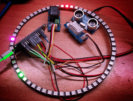
Honestly I will turn this into a project, not necessarily using all the bits in ths photo. I was simply interested to see just how much I could run at once using Tasmota – and sure enough, everything works including the Tasmota clock “scheme” 5. You can see in GREEN the HOURS display, in RED the MINUTES display and in magenta the once-a-second-updating SECONDS display. This is just like the clock I added to ESPGO.
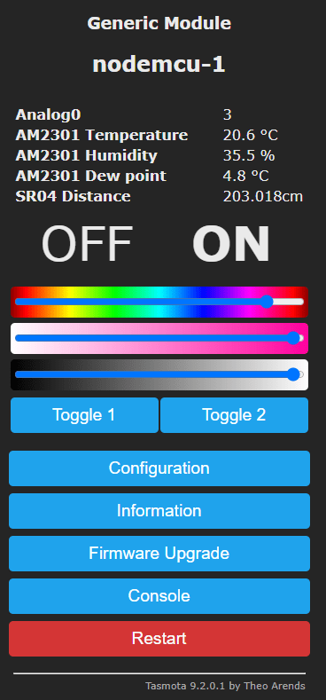
And all of that is happening while the SR04 ultrasonic sensor is being checked automatically for distance and the DHT22 for temperature and humidity, the analog input is being regularly sampled and a relay and LED are available for use, all without any additional software. I’m sure I could squeeze more activity in there, but that’ll do for now.
I built an infinity-mirror clock using a WS2182 strip, controlled using Scheme5 in Tasmota. It worked fine. Then due to a lack of space in my temporary accommodation I stopped using it. I built another smaller clock using the LED segments, similar to the above and found a 3D printable frame/stand for it but the data input needed to be at the bottom. I know I struggled for ages to find a way to make the 12 o’clock position be halfway round the circle from the data input, but eventually found how to do it. The ESP01 from the original clock got purloined for another project.
Now in a new house I want to use the infinity mirror clock again. I copied the code from the smaller clock and flashed it onto a new ESP01 and installed into the larger clock but now the input being back at the top, the display is out by 6 hours. Now I can’t work out how to get 12 o’clock to be back at the input position.
I know I could alter the time by six hours by using a different NTP server but I know it is possible to adjust the input position.
Can anyone help before I tear out what little hair I have left.
At least you have some left.. I long since lost my remaining locks – presumably due to the frustration of keeping up with Tasmota upgrades… 🙂
Solved it.
There is a Rotation command that you can issue from the console. So ‘Rotation 30’ is a rotation of 30 pixels, i.e. half the amount so 180°.
My problem was I was issuing it on the ESP01 that was already rotated. The amount is absolute not incremental.
‘Rotation 0’ was what I needed.
Magic.
Hi Pete
Have you ever published your Tasmota version of the espgo clock using an esp8266.
I know it would be quiet an undertaking but are you ever likely to produce an ESPGO that has been Tasmotorized.
Hi Cliff – maybe you misunderstand slightly- espgo is software – developed before Tasmota existed and still useful but not under active development. Any nodeMCU, Wemos D1 or similar ESP-112-based board running Tasmota can now run one of the standard ws2812b Tasmota presets one of which is a clock like the one incorporated into espgo. I’m updating this blog entry slightly to show the Tasmota clock “scheme” running on my desk…hope this helps.
btw, for every ws2812b related device, the excellent standard is WLED…
Sorry for the long delay, Cliff… ESPGO is the name of the software who’s code is still out there but which is no longer supported as Tasmota does pretty much everything ESPGO does (and a wider range of devices) so I stopped developing it. Any old ESP12 module will do for the clock..
I have a 12″ clock in my hall. It’s very accurate, runs for a year on a single AA battery and cost £5.99 at Argos 🙂
That’s nice Ian but you didn’t say what kind of clock 🙂 … got a picture?
Hi Pete
I need some help.
I running a esp8266 using Tasmota sensor-bin and have no trouble getting it work with a relay and bmp280 but no luck with ws2812 on GPIO12.
It runs and I can see a similar display as yours with the colour bars on/off toggle icons and the temperature etc.
But nowhere can I see the clock preset 5 you mention, how or where do I get from?
With Thanks
With thanks
Hi
So assuming you’ve set the WS2812 for the right number of LEDS (pixels 60) and turned it ON, it is: scheme 5
Find the schemes under LIGHT section here. https://tasmota.github.io/docs/Commands/
I have a 60LED strip WS2812 on GPIO15 but I don’t believe the GPIO number important. It comes up in the webui as toggle 2 as I have a relay on GPIO12 (relay1). Anyway it needs to be ON and that scheme set (non-volatile) and it should work.
Pete
Hi Pete
Thanks for the info.
After much trawling the internet and sorting the wheat from the chaff I did find what you have just noted.
All working ok! Very clever Tasmota.
Well, it looks like a clock 😉
If you can find the space I think you might find a CO2 laser does more of what you want. You won’t engrave/cut clear acrylic very well with an optical laser without using tricks. You might try a black coating (paint)on the surface. Try smearing it with washing up liquid (I’m not kidding!). I think your problem is that the material is transparent to the wavelength of your laser?
You are of course correct, Ian.Clear Perspex is apparently not easy with the solid state lasers. Well, I could always get some slightly grey tinted… and I have a new laser engraver to test as well, so that’s as good a test as any. Righto – thanks for the tip – I truly am a novice at the 3D printing and laser engraving – which is why I need to write about it as everyone has to start somewhere…
I will follow this up. Right now, getting materials is not that easy – I’m waiting for more phones and hasn’t Hong Kong dried up… meanwhilein our rural area of Granada – getting a choice of Perspex samples is probably going to be a challenge. If nothing else, back in the Northeast of England there were no shortages of places to get such materials – at least, not last year, I’d imagine some have gone bust by now, such is the world of Covid.
Hi Peter
I’ve used quite a few powerful diode lasers & they frighten me.
https://cordis.europa.eu/project/id/215280
However, I close the acrylic lid on my CO2 laser & I can watch it work, without goggles.
I live very close to an acrylic distributor who throw away loads of stuff. I must talk to them.
Hello, a DIY copy in color
https://www.instructables.com/7-Segment-NeoPixel-Clock-With-Countdown-Timer/
I LIKE IT. Right – weekend job…. ah, but I need Perspex. Actually I’m sitting looking at the LED display part – one of my many yet-to-finish projects…
Ahem, I know, that’s not clock mode – but I like pretty colours. One console instruction in Tasmota will switch that preset into a 60-LED non-volatile clock. Well, that and a centre opaque section to hide the nodeMCU and wires – and a circularly-engraved piece of Perspex. I’m still working on the “engraving perspex” bit, having savaged several pieces of wood now with my laser engraver – oh, thinking about iut, that’s not going to work… who wants a clock with burn marks. Keep thinking, Peter.