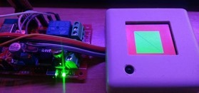
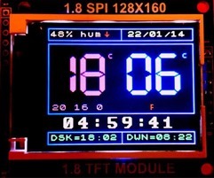
 I’ve seen a number of projects using an Arduino and an ESP8266 to drive LCD displays. You may know that my home control has used a 1284-based board (MEGA type) to run a nice Thermostat display for some time now. The displays look very pretty in the right box.
THIS article will tell you about the display but you’ve seen them on Ebay no doubt. https://tech.scargill.net/samsung-s6d02a1-based-lcd-colour-display-and-arduino/
Banggood do the displays (I can’t help thinking the price has gone up – at £3 inc postage – but still cheap) http://www.banggood.com/1_8-Inch-Serial-SPI-TFT-LCD-Display-Module-With-Power-IC-SD-Socket-p-909802.html
MAKE SURE you get the display marked 1.8 TFT module using the s6d02a1 chip – there are some marked differently and using a different chip which does not work with my software. Anyway, they are 160*120 and very bright and colourful displays, excellent for simple stuff.
 I’ve always wanted one of these to run on the ESP-12… on the Arduino assuming 5v you need series resistors for the outputs – as it’s a 3v3 device internally, but with an ESP you can run them directly. So, the device and it’s backlight go straight to 5v, the 4 inputs go straight to ESP8266 pins and the reset can go to the ESP8266 reset pin – again directly.
That’s the easy part – the software not so – there are not a lot of drivers out there for this board for the Arduino – one that does work offers a choice of hardware or software SPI and that’s where the magic comes in – if you eliminate the hardware SPI code it all starts to look quite easy. So yesterday I set about (with no anticipation of success) converting the code firstly from nicely object-oriented Arduino code – to basic C – and secondly to use ESP8266 port pins. I cheated slightly by using EASYGPIO to make the port operations a little more obvious but I don’t think that has cost too much in speed.
Anyway to cut a long story short at THIS point I’m off to the coast for a couple of days sunbathing and I’ll leave you with my work in progress. I’ve NOT added in the code to handle characters/fonts yet but I HAVE got this working completely reliably – drawing boxes and lines. Right now there is some setup data in RAM, I’ll move that to FLASH shortly (you need a function to access 8-bit FLASH arrays to stop the ESP crashing so I left that until last). Why bother with FLASH? Well, you’ll definitely need to put fonts in FLASH as they get big, quickly.
I’m assuming you’re programming in C – don’t ask me about getting this running in Arduino code or Lua.
Here’s the header https://bitbucket.org/snippets/scargill/EA9zd/qdtech-display-header-modified-adafruit
Here’s the C code https://bitbucket.org/snippets/scargill/qRbpL/qdtech-display-header-modified-adafruit
I’ll assume you already have a project running and just want to add this to it. I’ve reduced includes to a minimum..
My test includes a red screen background, a green box and a blue diagonal line. So with the includes this is all I put in my code (I slightly altered the init code to include ports (not including RST line as you fasten that to the ESP reset – hence needing only 4 port bits – you’re not stuck with my choice – the last two parameters are the screen size).
QD_init(4,5,15,12,0,160,128);
QD_setRotation(1);
QD_setAddrWindow(0,0,160,128);
QD_fillScreen(QD_Color565(255,0,0));
QD_fillRect(30,30,90,90,QD_Color565(0,255,0));
for (int qq=0; qq<160;qq++) QD_drawPixel(qq,qq,QD_Color565(0,0,255));
There it is – a starter only.. but it works – if this were taken to an extreme it would include character handling and hardware SPI – I’m guessing compared to Arduino use it would be pretty FAST..
Now if anyone wants to take this on and add the bells and whistles..
Oh and how would you run the data in FLASH? not so hard… here’s a typical FLASH-based array snippet.
static const uint8_t ICACHE_RODATA_ATTR kelvin[] = {
255, 51, 0, // 1000
255, 109, 0, // 1500
255, 137, 18, // 2000
And to access that…
// This routine courtesy Richard A Burton – way better than using 32 bit flash arrays (you can’t directly
// access 8 bit FLASH arrays directly – will crash the processor)
uint8 ICACHE_FLASH_ATTR read_rom_uint8(const uint8* addr){
uint32 bytes;
bytes = *(uint32*)((uint32)addr & ~3);
return ((uint8*)&bytes)[(uint32)addr & 3];
}
Typical use
rgb.green=read_rom_uint8(kelvin+kel);
rgb.red=read_rom_uint8(kelvin+kel+1);
rgb.blue=read_rom_uint8(kelvin+kel+2);
So you can see it won’t be TOO hard to get a load of font data into FLASH – sure, it’ll slow things down a little accessing it – but how that actually affects operation is something we’ll discover in the future.

Visits to this site ALWAYS cost me money.
Hi guys, this site is just what I was looking for! Great! I’m working on a couple of projects, which include 1.8″ displays (2.2 are on the way). I’m currently using Arduinos, which are soon to be replaced with ESP8266 boards.
Glad to be of service. We’re working on a little Nextion board for ESP-12 – more on that when the boards turn up most likely this week.
Glad it’s working well for you guys. I will make the suggested changes. Someone did adapt ILI9341 driver to the ESP its common in the 2.2″ displays. Here is where I read about it http://www.esp8266.com/viewtopic.php?f=32&t=5560
Well, all is well with the TFT driver but.. .I just downloaded the latest GFX library – and the demo works fine – no problem.
I reduced the demo down to simply clearing the screen and putting up “Hello world”… and that was fine… then I notice that the GFX library finally has some great fonts – all in the fonts directory..
I added
#include
No problem
But then after clearing the screen I added…
tft.setFont(&FreeMonoBoldOblique12pt7b);
and now the test does not work
testdrawtext(“Power up” , ST7735_WHITE);
Remove the setfont and it works – anyone got this lot working? It would make SO much difference..
Setting the ESP CPU speed to 160Mhz (in Arduino IDE – tools menu), gives +- 50% perf increase compared to 80Mhz.
I can get almost 75 FPS@160Mhz for full screen fill and 50 FPS@80Mhz (using benchmark provided in PDQ library: https://github.com/XarkLabs/PDQ_GFX_Libs/tree/master/PDQ_ST7735/examples/PDQ_graphicstest)
I ordered some 320*240 ILI9341 2.2 display yesterday. It should also work great with this ESP !
The bigger displays I have run (on Arduino) as “TFT01_22SP” – I just tried just on the offchance that they would be compatible with THIS library – no chance… white screen. I’ve searched around for an ESP compatible library with example – but no. I wonder how much difference there is in the two..
I cannot believe how fast 200*160 display this is on the ESP as against the old Arduino – yet still using almost the same coding – I really need to get this running on the larger 240*320 display- I THINK that used another library… that long ago not sure. Anyone out there got the larger display running using the Arduino environment for ESP?
WELL – I put the the Arduino environment and after getting the pins wrong several times eventually go the display running – FAST doesn’t cover it – and with the modification suggested by Beniot J – it absolutely blows the Arduino out of the water!!!!
Now I wonder what’s involved in getting this running with the slightly larger QVGA 2.2 TFT SPI 240*320 display (TFT01_22SP)…. the red one often on Ebay. Any ideas? That display was just too slow on the Arduino but with this – well, you could make an oscilloscope!!!
Peter, what should the pin connections be on my esp8266 03 and the 1.8 inch tft, I find different layouts….
Pete, you inspired me to get this working..
I modified the latest Adafruit ST7735 library for Arduino-ESP It works great, including all functions and Hardware SPI. Runs at least 10 times faster than on an Arduino. I posted the Library on Github if anyone is interested: https://github.com/norm8332/QDTech_8266
Not tried it yet – I’m working on some other issues but THANK YOU for taking the time to do this – that is EXCELLENT… I will hook one up as soon as possible,
Pete.
Thought I’d replied to this but it has disappeared.. all my projects in Eclipse (using the unofficial Dev Environment on Windows) are .c files – not .cpp files.. do you know something I don’t or was this done in a different environment. Not sure that I’m sure how to integrate that with my .C files…..
Pete.
Pete, This is an Arduino IDE Library for use with https://github.com/esp8266/Arduino ESP8266 board Manager Add-on. I should have made that more clear for those who don’t know about it, It allows direct programming of the esp8266 from the Arduino IDE. Some Arduino libraries are supported and some are not until ported.
Hello Norm, thanks for your library adaptation. This is really great !
Here is a small modification that increase again the performance by +-3 !
In QDTech_8266.cpp, replace :
SPI.setClockDivider(SPI_CLOCK_DIV2);
by:
SPI.setFrequency(40000000);
The SPI clock will be set to 40Mhz instead of 8Mhz !
Kr,
Benoît
Oh I HAVE to give this a shot….
This does not seem to work any more with the latest versions. SPI_CLOCK_DIV2 seems to be the best I can get ?
Am I wrong?
or save yourself a whole lot of trouble and use this £3.10 – 2.2″ Screen and library
http://www.aliexpress.com/item/2-2-inch-TFT-LCD-module-SPI-serial-interface-module-240-320-Minimum-occupancy-4-IO/1797416202.html
demo here:
Oh hell that’s WAY better (though by the look of it no faster – would be nice to see someone implement the HARDWARE SPI!!! Thanks for that, I’ll order up a display.
The referenced library says it is using HSPI.
Hi Tony
This looks great.. but that const stuff for the fonts is not putting this in FLASH – did you leave them in initialised RAM or have you change them to go into FLASH – there is a way but it means accessing each character by a short routine… not sure what effect that will have on speed. I’ve already used up a fair bit of RAM.
Pete.
To be honest, I have programmed a spare esp21 with the demo code from Cherts and at the moment I haven’t taken it much further. I have been busy building my IoTBox(es) – this screen might be in IoTBox v2 :-).
There are details for IoTBox on http://blog.spants.com
example here -> http://www.cb-pc.eu/graphicstest-esp8266-1.8-tft-spi.ino
BC, I tried this and it will not work without modification. The QDTech board has a different chip : Samsung S6D02A1.
Tried this on ST7735 TFT with Adafruit libs, but display initialization gives me an Exception (28). I will load this project in Eclipse IDE and try to find the reason.
//ST7735 display
#include // Core graphics library
#include // Hardware-specific library
#include
Hi Pete,
For the arduino esp8266 environment you can use the Adafruit-ST7735 & Adafruit-GFX libraries without modifications (if i remember correctly)
snippet from my code:
//ST7735 display
#include // Core graphics library
#include // Hardware-specific library
#include
/*
* ESP8266-12 HY-1.8 SPI
* GPIO5 Pin 06 (RESET)
* GPIO2 Pin 07 (A0)
* GPIO13 (HSPID) Pin 08 (SDA)
* GPIO14 (HSPICLK) Pin 09 (SCK)
* GPIO15 (HSPICS) Pin 10 (CS)
*/
#define TFT_PIN_CS 15
#define TFT_PIN_DC 2
#define TFT_PIN_RST 5
Adafruit_ST7735 tft = Adafruit_ST7735(TFT_PIN_CS, TFT_PIN_DC, TFT_PIN_RST);
Works like a charm 🙂
something whent wrong in copy & pasting ->
//ST7735 display
#include // Core graphics library
#include // Hardware-specific library
#include