 Voltage and current monitoring
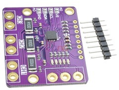
The INA3221 or rather one of the boards based around it, allows for a single power input and up to 3 power outputs –each monitoring voltage and current and all done via I2c.
You can (almost) think of this as a triple INA219 – the bidirectional current power monitor. If you recall, a little while ago, I added the INA219 to my ESP8266 software. I thought the INA3221 board might be better than three of the INA219 boards – but read on…
The difference here is a saving in cost – saving in number of devices you need to address and saving in size. I bought this one from AliExpress but you can get them on Ebay etc. I paid £2.15 – which seems reasonable.
Meanwhile over here I discovered some software to test the board with… it gets better, the software also worked first time – without even as much as a pair of I2c pull-ups.
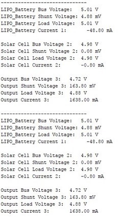
And from there, for a while it all started to go downhill. From my stabilised power supply I put out 5.2 volts set to put out a maximum of 3 amps, just to be safe. Here is the output with no load:
Pretty much as you’d expect, 5.25v is near enough as my power supply only has one digit after the decimal point (got a much better supply on the way).
The three outputs showed pretty similar results – I’d have preferred if they’d shown 0 amps but that’ll do. I took a large 2 ohm resistor – which you might reasonably expect to take 2.5 amps when faced with 5v. I put it across my supply – and sure enough – 2.32 amps. That is well within the likely 10% tolerance of my test resistors.
The voltage out of my power supply didn’t budge – and stayed rock steady.
After I recovered from burning my thumb and allowing the resistors time to cool off, I repeated the experiment more briefly and nothing had changed.
I picked one of the outputs and put the load across that instead of my power supply.
The input voltage was down to 4.98v which is fine because I will have lost power along the lead to the little monitor unit.. I had attached the load to output 3 which was showing an output of 4.73V at 1.638A.
Something very wrong there… my power supply was saying 2.1 amps was being used… the software was saying 1.638V voltage drop. I checked the library header – it said that the default resistor was 0.1R – I checked the board, sure enough R100….
And then reader NEIL wrote in to point out the mistake – I had ASSUMED these chips were similar to the INA219 – but they are not – there’s a maximum input voltage to the chip of 1.163.8 mV – put that through the default 0.1R resistor and you’re looking at 1.1A or so MAX. So – if you’re happy with that, fine – if like me you’d rather have over 2 amps AND a lower voltage loss, it is out with the fine soldering iron and replace those three 0.1r resistors with 0.05r resistors (remember to ensure you get high accuracy resistors or you’ll have to mess with calibration). The advert didn’t actually state the maximum voltage reading of the chip – I just made assumptions.
So rather than sit about, I tested the INA219 with the same kit, using software from here – and sure enough – 2.2 amps – absolutely correct.
New Beginnings
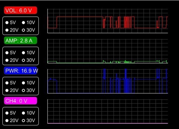
So then I started thinking about making a little voltage/current meter using one or more of the INA219 boards – and as I had one hooked up anyway…. I looked at graphics – but then I figured I’d always be at a PC screen – and noticed an article on the PROCESSING system – available for Windows and Linux…. the first attempt was a partly modified USB Arduino voltmeter. Well, GUTTED more like it – here’s what it looked like after an hour or so – ignore the last reading.
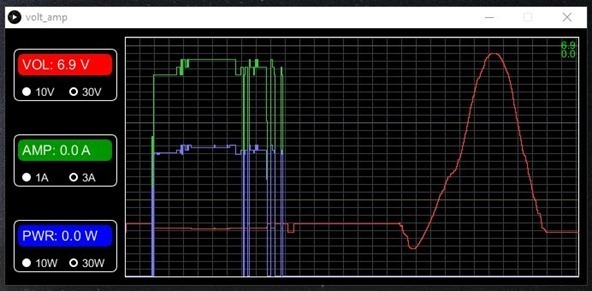
I’m not sure why the origial author displayed voltages as points – it really didn’t look good – but that was easy enough to fix and so my first working version is shown above. Do remember though that any such system involving a 0.1r resistor to detect voltage drop – and hence measure current – is always going to produce that voltage drop and lack of stability in the output – beats me why they don’t use a much lower voltage. There is no way around this…
So consider 0.1r… you feed it with, say, for simplicity 10 volts and draw 1 amp. So that is 1 amp going through the 0.1r resistor – you are GOING to lose 0.1v. Off-load you lose nothing… so your super stable supply, assuming a variable load, how has a 0.1v ripple on it. Decide if that is important or not before using these boards. At 2 amps it gets worse, 0.2v.
It may be that the INA3221 is better (given that you are able to replace the 0.1r with a 0.05r resistor – or solder another 0.1r on top) even if you only use one channel.
Of course the above was just a starting point. Several hours later, having pulled out most of the original code to get just exactly what I need… a single working area with the three graphs in one. This is currently like a car before they put the decals on it… I’ve much more to add but it’s taking shape and is already useful. Here’s the latest version…
And here’s a short video to give you a better feel for where I’m up to..


Hi,
They say there are no dumb questions but I may have one. The 3 larger holes, 2 at the ends of the resistors and 1 in the corner, I am guessing they are for mounting screws? If so, what size are the holes and are they connected to ground?
thanks
i guess for my 200a drain i’m better forgoing the .1r resistor lol, and getting a metal based current shunt, they all seem to be a common 0.75mv at 50a or 0.75mv at 100a and even at 200, so they follow the standard of giving a full scale swing on an old 0.75mv moving coil meter, i guess some hacking could be done to attach an ina219 or ina226 to one
For a 200 amp load perhaps a current transformer would be a better choice, being non invasive. There is a very good write up on CT’s on the ‘OpenEnergyMonitor’ web site using a CT with an Arduino. I have used information from this site with good success for current monitoring on 240 VAC systems. I did find that with LED floodlights the mains waveform is so distorted that the current measurements were meaningless.
Another option with the 0.75 mV shunts is to use an I2C ADS1115 ADC. These work well with ESP8266 / ESP32 devices that have a limited internal ADC range.
There are also the PZEM-004T devices, although from my point of view not as electrically safe as I would like.
If your power supply has a sense input, connect it after the current measuring resistor. Then the power supply will compensate for the voltage dropped across the sense resistor.
Hopefully the IC can be connected in such a way that it measures the actual sensed output, not the voltage before the sense resistor
Peter – would you happen to know the package size of the resistor for the INA3221?
Thanks and hope the spring is treating you well.
I don’t know the size off the top of my head. If the resistors I used surface while I’m unpacking, I’ll leave a note in here.
Thanks, my INA3221’s are taking a slow boat from China and am hoping to not add to the delay by having to wait until they arrive to order some resistors.
Thanks again
Glenn
Hi! How about accuracy of your pcb? I got INA3221 pcb from China, and it show in my case 0.202A, but volttage on shunt R100 is 0.196V. What is wrong? I measure voltage by 0.1% digital multimetr.
Duff chip perhaps?
Hi! Thanx for answer! I think so. But today I found interesting information about INA3221 Error Analysis: http://www.ti.com/product/INA3221/toolssoftware – there is the error calculator. As I understand, error depends from few parameters and can be as big as few %%, especially in low current range…
Hi Wes, maybe this helps
http://startingelectronics.org/software/processing/software-voltmeter/
I’ve been playing with the INA219 too and an interested in your “PROCESSING” code. Do you have that code posted somewhere?
The library for arduino can download
https://github.com/switchdoclabs/SDL_Arduino_INA3221
If you want to modify the module with three independent readings, you can have three independent power sources with different voltages
https://kacitran.blogspot.com/2018/10/ina-3221.html
Hi Pete, very interesting. May I have the link to the website containing the sketch for the PROCESSING application or even your modified code?
Thanks in advance
Wolfgang
The video should give an idea of how far this has gone. I envisage putting a couple of up/down buttons on the Arduino clone to alter the speed of sampling – and sending that back to the PC program to display monitor rate…. then I need to fit the whole lot into the smallest feasible box with air vents.
hi Pete,
looking at the data sheet for the INA3221 the max shunt voltage is
Full-scale range = 163.8 mV so your sums add up but the 0.1R resistor is too big to measure anything over 1.6A as you will hit Full-scale on the input.
change them to 0.01R or a value to give just less then 163.8mV 20% or so above the largest current you want to measure.
regards
Neil
AHAH… I ASSUMED that like the 219 this had a maximum current of 3 amps or so…. but looking at the advert – they don’t actually specify current. My fault for not looking more carefully and thank you so much, Neil for that information. As it happens I’ve ordered some 0.05r resistors – so that will give 3.2 – which means I can measure 3 amps – AND get lower drop…. that’s marvellous – thank you. I’ll amend the blog (so if anyone reads this and cannot understand why Neil wrote this – I was assuming 3+ amps capabillity due to not reading the advert correctly).
On Adafruit’s site (https://www.adafruit.com/product/904) it says: “Since the amplifier maximum input difference is ±320mV this means it can measure up to ±3.2 Amps”