
I have a solar power setup for my external lighting here in Spain and for some time I’ve been having some kind of issue with (what I’m now fairly sure is) deteriorating battery capacity.
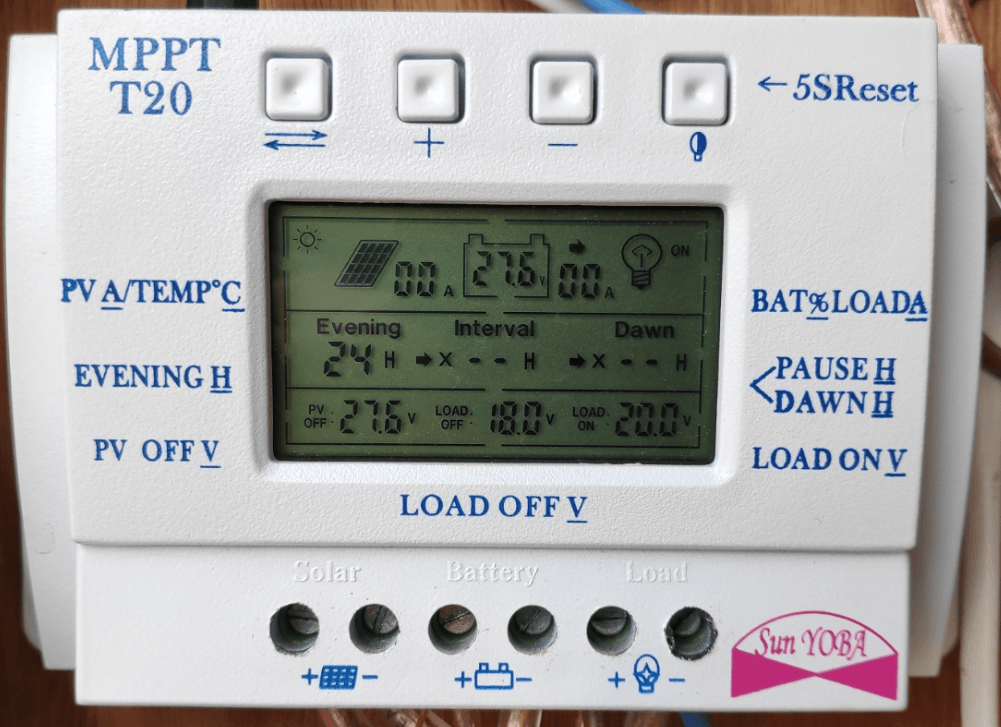
My twin 100AH deep-discharge camping batteries are powered by a 250W 30v (or thereabouts) solar panel and a standard MPPT T20 (more the £20 than the £10 type) and this arrangement has been running for maybe 4 years now. Over the past few weeks I’ve noted the batteries not even lasting the night.
So, after the usual cable checking operation, I recently started experimenting to see where the problem lies – options included the solar panel, the MPPT unit and the batteries (and that could be one or both of the two 12v batteries, running in series for a nominal 24v installation.
In narrowing down what my problem is, the first step was to check out the solar panel – that was easy because on offload voltmeter test, it pumps out 30v in autumn sunlight – and if shorted by my multimeter, it pumps 5 AMPs into the meter – an hour before dusk in November here in largely sunny Southern Spain – so mid-afternoon it will put out a lot more than that.
The second thing to check was the charging arrangement – I can find nothing wrong with that.
That leaves the two lead-acid batteries – I decided I needed to monitor the batteries separately and also charge them separately via mains power for a time – while continuing to actually use them serially for nominal 24v output – to see what happens.
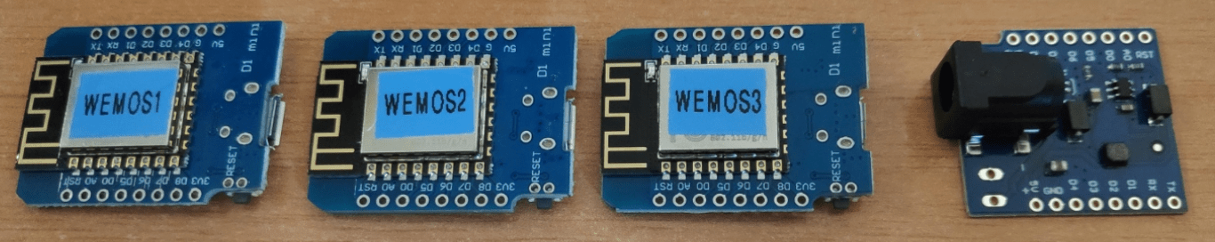
I’m an old hand with the Wemos D1 Mini boards and with the free, open-source software Tasmota (at the time of writing, v9.1.0.1 is out there) – and the ESP12 has an analog input ideal for the job of long-term voltage monitoring – all I needed was something to do a stable job of converting a very variable 12v battery output down to 3v3 for the Wemos D1 – and it turns out that AliExpress do both the Wemos D1 and the piggyback switched-mode (and hence efficient) power modules very cheaply.
My D1 Minis came earlier this week, the power modules arrived this morning and all I needed were some simple resistor divider pairs so that I could easily build a pair of totally independent 24/7 voltage checkers – one for each battery.

There are of course many ways to do this but I like using the Wemos boards hence the above. From memory, I knew the D1s have a resistor divider in there already to max out the analog input (value 1023) at around 3v3.
Wemos D1 and installing Tasmota
At the time of writing, Tasmota has a new development version – 9.0.0.3 (the one WITH the bug fix that came out at the start of November 2020).
I’ve recorded a short video above – covering using Tasmota on the Wemos D1, I hope someone finds it useful.

I plugged the first Wemos into a USB lead, took the first COM port that appeared on my PC, selected “development image” Tazomotizer automatically grabbed the latest TASOMOTIZER (v 1.2) for Windows 64, I hit the “Tasmotize” button, awaited further instructions, removed and reconnected the USB lead and then selected “Send config” to give the board my WiFi and MQTT credentials.
To check the A/D roughly, I put a 1.5v new AA battery between ground and the analog input – and got a varying value from 430-480 – bearing in mind I’m still using unstable USB to power the Wemos. That averages out at a reading corresponding to 1.5v input from the AA. The power shields arrived this morning… see photos.
NOTE: this blog entry is a work in progress and will be changing by the hour as I add or improve it.
Actual Voltage Testing
I happened to have some 1K and 4K7 resistors handy and used those for the dividers… Tasmota has a command AdcParam – VERY handy… I put the dividers onto the first Wemos board with the input fastened to the power input of the Power shield. That of course produced a value in the 600s.
I settled on using Tasmota command AdcParam 6,0,1023,0,1780 – which is non-volatile. Now with a battery voltage randomly set to 12.630 (I have a very accurate meter as you’ll see in the blog elsewhere) I get 1264 – narrow both of those down to 1 decimal point and you get 12.60v and a value of 1260 on the Wemos – good enough. .
I need 2 of these Wemos-based units – boxed and perferably protected against major temperature changes – That last “1780” value will differ from device to device. I also need a third checker to go into my car (no, not under the hood as that will screw up the WiFi – I wasn’t born yesterday). On my second device the value had to be 1800, on the third, 1750.
Now – THIS is important – in the CONSOLE of Tasmota you need 2 lines – one to set up the new ADC conversion permanently with a rule – the other to make sure that rule is turned on.
rule1 on SYSTEM#BOOT do adcparam 6,0,1023,0,1780 endon
rule1 on

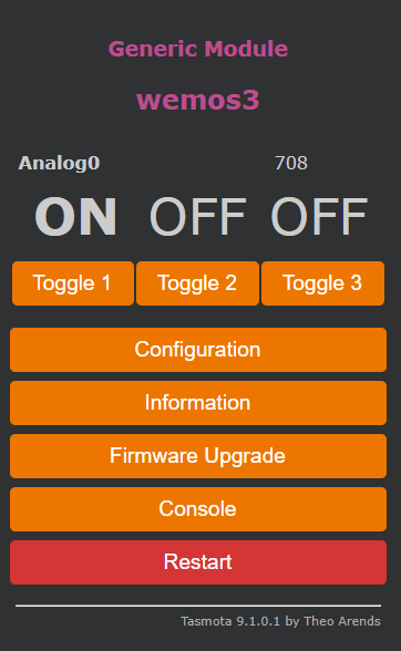
The value 1780 above will depend on your resistor values of course as I covered above. You’ve just seen the raw ADC value above (see that 708 in the image above) – now see the new value (*see the 2164 in the image on the right) corresponding to a 12.6v battery after I set up that rule.
It is also important to note that just after setting these up I OTA’d from 9.0.0.3 to 9.1.0.1 – and got my original value before correction. I’m not sure why the OTA lost the ADC settings (there are several resets during OTA) but I re-entered those two lines and all was well. Best not OTA when this is in service?
The video above shows getting the Wemos running from scratch – and of course I got carried away and added 3 outputs and buttons as you’ll see in the above photo – for no particular reason – I hate to see GPIO go to waste – I’ll remove them with the Tasmota WebUI when I actually deploy these voltage checkers as they won’t be doing anything else. I’m making a note here about the buttons up there “Toggle 1” etc. You can now, as an aside change that text with:
WebButton<x> new text
for example
WebButton1 MyToggler
But I digresss…
Lead-Acid Battery Charging:
Simultaneously I was/am experiencing a battery capacity issue with my car and having settled on a TM-D28A Lithium-powered quick-starter unit (see my quick review) to get me out of any jam, I was thinking about high power 12v battery chargers (as against starters) and hit on the idea of asking Banggood to send me a couple of decent modern chargers to compare and pick the best one – blogging about both in the process, the idea being to use both of them for the solar installation and that would also give me a decent car charger if needed.
I selected the 5 best-looking chargers from Banggood’s ad with a view to obtaining a couple to compare then use. What actually happened is that Banggood sent all FIVE of them.
I can now select the best two chargers and give them the job of keeping my batteries separately charged until I finally narrow down the cause of my solar capacity loss and if necessary replace the (rather expensive) batteries.
The 12v (or 12/24v) chargers I have available are:
See the links above for full details on the chargers. I’m still working on the solar battery charger side – we’ll see which do the best – more soon. I can tell you that at least one doesn’t actually specify on the unit or box what the current output is. Odd.
Meanwhile:
For the sake of it, let’s take a look at that last charger, the SUOER 12v 10A charger. I have 2+ year old a battery in our little runaround car – the Spanish “Seat Ibiza” – a battery which has sat through two winters out of use and one which I don’t trust. It has died on me 3 or 4 times times this summer.
Two weeks ago, I gave the battery a good overnight charge on an old 4A charger (with a big transformer, so, last century) which belongs to a friend of ours. The car has actually been fine ever since – but I checked this afternoon and the battery was 12.4v, not bad but hardly FULL – not too surprising as, during Covid lockdown our shopping trips are very short.
I pulled out the new SUOER charger and plugged it in to mains power and to the battery. WELL, this was interesting. Indeed it almost warrants it’s own article but here goes:
Starting below – with the charger connected but NOT plugged into the mains – the display alternated between 12.4v@0.0A and 100%@0.0A – not sure what the 100% was all about – definitely not a 100% charged car battery.
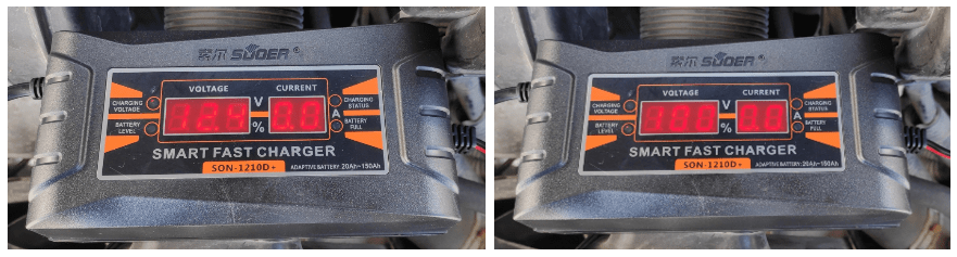
I had a shed load of other photos for you but due to camera strobing effects – we’ll give them a miss. I plugged mains power into the SUOER and lo and behold – after maybe 15 minutes I checked and… 12.8v@12A and 21%@12A
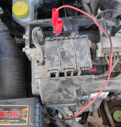
Ignore the filthy state of my battery – it’s been a VERY dusty summer. The first thing that grabbed my attention was the lack of heat at 12A from the charger – and more importantly from those (integral) thin charging leads shown above.
Talk about opening a can of worms… I grabbed my (not-cheap) HoldPeak HP-770D 5-digit multimeter on the 20A(DC) measuring range and inserted it in series with the red + lead to the battery. Now here I’m at a loss – that single operation immediately reduced the charge current to 6.5A according to my meter and 9.6A according to the charger. Maybe you’re supposed to use special (not supplied with the meter) leads to check high current. Either way the meter and charger should have been consistent. I quickly tried a cheap and nasty 3.5 digit multimeter I use for non-critical work – similar readings.
Having decided this was going no-where, I went back to meter-less charging and the reported charge went back up to 12A – again according to the SUOER charger. I started on this blog update and maybe half an hour later – 13.1v@12A and 20%@12A
I left the charger in place and started a tirade about an unrelated review gadget making a noise – and lost all track of time. After maybe 3 hours, I returned to the charging scene. 14.2v@2.8A and 70%@2.8A – I’m assuming most of that time was spent at a much higher rate of charge.
Another half hour and the charger said 13.7v@0.0A (ie 100% charged – done). I removed the charger, inserted my HoldPeak meter across the battery – that value almost immediately dropped to 13.5v. After 5 minutes the value had dropped again to 13.3v and after a further 15 minutes appeared to be stabilizing at around 13.2v
At some point I’ll return to this and replace both METER and CHARGER leads with something more substancial (AND I’ll compare with other meters in my list) – I wonder if that will help explain the difference between the meter and charger CURRENT readings.
Whatever, that SUOER is able without breaking any kind of sweat of outputting, I’m thinking, between 9A and 12A and is therefore worth keeping in my car-maintenance cupboard corner. I already have two of the Enusic chargers earmarked for my solar battery testing but that’s for a later time.
Update:
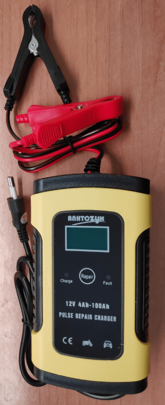
The Enusic 12v 6A charger arrived marked “ANHTCZYX” (Updated version 5.0) and features pulse repair charging, over-voltage protection, auto stop, temperature detection and more.
The manual comes in a variety of languages including English. The charger claims to handle batteries with capacity from 4AH to 100AH, works from 100v-240v and has winter and summer modes as well as handling all the major types of lead-acid batteries.
The unit weighs under 0.5Kg and measures a mere 22*11*4.5cm. Mine has a 2-pin EU plug, plastic construction and looks solid.
In conclusion:
When I started this I wondered how I’d ever use more than one charger. WELL – how things change… we can’t get back to the UK right now to get my new solar batteries, so one charger is in full time operation keeping my depleted (24v total) solar batteries topped up (partly they are shot, partly not as much sun as usual), I’m giving one car an all day charge every couple of weeks as I still don’t trust the battery, one neighbour had an ancient low-current charger and the other bust his – so in fact my chargers are in good use – I just saved the last neighbour from buying a new battery by insisting he give his car battery a good all day charge (the battery was low but not dangerously low). He’d been doing nothing but short runs in the cold weather and that’s asking for trouble. The battery is now fine.
Now I’m looking to do something similar but different – a modem/router 12v UPS using lead-acid car battery + charger + wemos D32 with tasmota.
The idea is to charge the battery overnight on cheap leccy, or during the day if I am exporting solar power >4amps, when battery is full switch off charger with D32 output. Do you recommend any of those chargers listed above.
Modems are 2x BT homehub5 which run on 12v @1A each and always on
Hard to make recommendations 18 months later – specially with the current shipping issues. I’mnow all out of solar opanels after my main Spanish panel dropped off the roof and smashed itself, but given the current cost of electricity both in Spain and the UKm I’m inclined to charge batteries overnight for running Pergola and other outdoor lighting – I’m taking 2 new leisure batteries back with me. For reasons beyond me, both batteries and solar panels are more expensive in Spain than the UK. I have a couple of always-on routers (the second can handle a SIM to provide backup 4G), a 16 way switch and a WIMAX-type modem over there, I’m planning to use them via batteries for 2 reasons, unreliable rural electricity and taking advantage of the cheapest of the 3 rates (ie overnight) in Spain. When the power goes off (most often just for a matter of minutes) due to storms, the village WIMAX-type dish often gets turned off – so a power+broadband backup solution is essential.
I should warn folks that the 12/24v EFAST charger turned out to be rubbish for my purposes though it is probably fine for 12v 8A charging.
When charging my failing 24v solar battery arrangement (two 12v batteries in series) it made a complete mess – working for a few days of no sun then eventually embarrassing the hell out of me in front of friends – as it failed to charge the batteries when they dropped to a total of 18v, it decided that in fact this was a FULLY charged 12v battery and started setting off a loud audio alarm which has no OFF button (as far as I can tell).
Had it not been so “clever” and instead used a manual 12/24v switch it would be fine but for my purposes – I’m back to using a completely inadequate 26v 2A desk supply – the very thing I was trying to avoid.
9v per battery? They’re zombies 🙁
Fully charged – off charge for a lead acid battery is 12.5V so the reading of 100% @12.4V is not far off given the resolution.
The next tool you need is a hydrometer to measure the acid strength, my bet is one of the end cells is low
Check for sulphation, where white sulphur salts coat the plates, the pulsing charger may help reduce the build up
Hello Pete.
I use a lead acid powered horticultural sprayer to put nutrient down on grass; it’s a job that takes a full day. I start with a fully charged battery, run 8 tanks until the battery is discharged, put it on charge over an extended coffee break – it’s not fully charged so I only get 5 tanks, stop for lunch and full charge, and repeat in the afternoon.
The supplied charger is an unbranded, 4A ‘intelligent’ model that uses constant current, constant voltage (CCCV) charging with a maintenance ‘top up’ mode. There is information about this mode at https://batteryuniversity.com/learn/article/charging_the_lead_acid_battery
For this to work the charger needs to measure the battery terminal voltage to determine the state of charge and mine pulses the current, I guess to measure the voltage in the off phase. My DC current measurements using a series meter showed about 3.8A in the CC mode, not the expected 4A, and a small AC ripple current. I checked the voltage across the meter series resistance and the current was pulsed. I concluded that the charger is spec’d at peak output current not the charging current.
The meter series resistance may alter how the charger determines the fully charged point where it switches to maintenance/top-up mode. With mine there is a small difference between the final charged voltage (after the battery has been allowed to stand) using normal charging and with the meter in the circuit; though my meter is 15 years out of calibration and the measurements were made on different days in an unheated workshop!
It might be worth trying a hall effect current sensor which should have a lower series resistance than your meter and gives a voltage output for your WEMOS monitor. Bangood sell them with pass through currents up to about 100A – search for ‘hall effect current sensor’
Andy
I’ll do that this afternoon