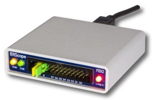
Let’s face it, if you want an oscilloscope and logic analyser that fits in your shirt pocket, your choices are a tad limited.
Regular readers may recall that way back in 2016, I did a short review of the BitScope Micro, a VERY portable circuit board which, coupled with suitable software for the Raspberry Pi or PC, acted as an oscilloscope or logic analyser. Well, this is it’s “big” brother.
Where the BitScope Micro was a circuit board covered in plastic, the Minis is more of  a “proper” mobile bench tool if a very little one.
The Micro had an analog bandwidth of 20Mhz which was barely enough for me – the Mini sports a more than adequate (for many projects) 100Mhz bandwidth. Here’s the spec:
- 100 MHz Analog Bandwidth.
- 40 MSps Logic Capture (25 ns).
- 2 Analog Oscilloscope Channels.
- 8 high speed Logic Analyser channels.
- Serial Protocol and Logic decoders.
- Windows, Linux, Mac & Raspberry Pi.
- Waveform, logic and clock generators.
- RF & Baseband Spectrum Analysers.
- Pocket sized, USB powered.
- Power, Ground & Control
The unit can provide both 5v and 3v3 outputs as well as I/O and clock signals so it can power, control and even clock logic circuits.
Of course – any non-display system like this can look good on paper – but this is backed up with a PC suite of programs (also on Mac, Linux and Raspberry Pi) and the software is free so you just pay for the unit which comes complete with probes.
This single photo pretty much says it all.
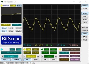
On the software front you get a mixed-signal logic analyser, a digital sampling oscilloscope, a waveform generator and more.
One particular interest for me was the logic analyser as I do a lot of development of I2c and SPI on the ESP8266 and my software never works first time – without being able to visualise the data, life can get pretty miserable.
Above is an example of use of one of the software tools, the analyser, able to handle CAN, SPI, UART and I2C. This is shown on Mac. Now of course you can use these tools on a low res screen such as a Pi might use but given the amount of information here, I think I prefer a large screen.
Opening up
On opening up the package, the BitScope Mini felt a lot smaller than I’d expected (of course the size is stated on their website) – the unit fits comfortably into the hand. I received the bitScope plus adaptor for scope leads. Sadly I forgot to order the scope leads but I had one lying around. I downloaded the software for the scope, the analyser and the meter from the BitScope site. Current version of BitScope is 2.8 though a 2.9 BETA is also available.
The Scope software
 Maybe my expectations were high, after all, it has been 18 months since I reviewed the BitScope Micro. The DSO software is, well, ok. It does the job, looks simpler than earlier photos I’ve seen but then that might be because they’ve removed un-necessary panels. I noticed that when I shut the scope down and started it up, my settings were not preserved. I went off on a hunt for information.
In April 2016: “persistent state is a feature that’s coming in DSO 3.0 (along with a range of others). This will include the ability to save and restore most user adjustable settings including probe attenuation. It will preview in the DSO 2.9 development releases in a few months time.”
At that point, I decided to grab the BETA software as lack of persistence is a pain.
What’s in the box?
The package came complete with the BitScope mini hardware and a USB lead. I had also ordered the Smart Port 01 – essentially an adaptor to give the sockets necessary to plug in a couple of scope leads. The scope leads were not part of the package… my mistake.
Software
It is of course software that is going to make or break this as otherwise this is just a little matchbox.
First Contact
I did what I guess many others do when starting up an oscilloscope for the first time – stuck my finger on the end of my (borrowed from elsewhere) scope lead and sure enough, the display came on and showed a pretty decent signal and correctly identified it as 50Hz (UK).
I have to say there is some LAG. From putting my finger on the scope lead to getting a reaction was somewhat under a second but quite noticeable. I suppose I’m used to my old 50Mhz analog scope which would respond IMMEDIATELY and appreciate that the scope has to collect a screen-full of information. Clearly as against a stand-alone unit, this has to collect up data via serial (USB2) before displaying it.
The Scope software
There are a number of packages available including BitScope DSO, BitScope Logic, BitScope Meter, BitScope Chart, BitScope Proto, BitScope Console and BitScope Server. I was only interested in the first three.
The “BitScope DSO” is a general purpose 2 channel scope software which also features a function generator that can generate signals up to 250Khz and all the way down to 5Hz and indeed at 50Khz the signal bears a good resemblance to a sine wave. At 250Khz however, it begins to look exceedingly triangular (I checked on 100Mhz digital scope) and over the range the output level seems to vary, diminishing as the frequency rises.
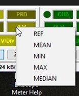
Similarly with the square wave output which seemed to be good up to about 20Khz. Some features of the BitScope software seemed strange to me – I’m used to having options of AC or DC coupling – but according to this, selecting REF is the same as DC coupling –  which left me wondering why a battery attached to the probe tested that moment to be sitting at 3.9v showed up, no matter what I did, as 2.28v in one direction and –5.5v in the other. Adding the two and dividing by two gives 3.89 – the right answer but at this point I am damned if I can figure out why the offset.
No doubt someone will write in and clarify. Still at least I’m happy that somewhere, the unit is giving the right answer. The problem is that the link I gave you shows options of AC, REF, MEAN, MEDIAN and MANUAL – and in the scope software right click menu – that last option is simply not there.
I wrote off to BitScope and I have to say the answer was pretty quick…
“A BitScope has a fixed voltage span that it can see, and by default this is set to a range where signals can be seen above and below the zero line. To make fixed voltage measurements you should move the offset down by about 2V – which will extend the positive span – making it more suited to DC measurements. The peak to peak range of the BS10 begins to lose accuracy when taken past about 10Vpp. This is fine for typical signal measurements, but should be offset for unipolar voltage measurements.”
I can’t fault the service but I can’t help thinking there must be an easier way just to measure a voltage. On a typical scope – and I’m sitting in front of two – you set to DC, put the battery on the meter, set the expected range and that’s it!!
The Meter Software
Concerned that I could not figure out the DC measurement on the scope software, I went to BitScope Meter – a simple program. I now have a precision voltage reference and ran 4 tests on the Bitscope at 2.5v, 5v, 7.5v and 10v.
Results: mean – 2.665v, 5.2v – and of course the maximum range without an attenuated scope lead (I used a logic lead) is 5v5. Not stunning.
Before heading off to the logic analyser software I checked with BitScope that my currently running tests with an FTDI and a NANO microprocessor were operating properly – I was sending ASCI data at 115K from the NANO to the FTDI constantly. I figured that was as good a test as any. It looked ok on the scope.
The Logic Analyser
I switched my leads over to logic channel 0 and connected my running 115k bit no parity 1 stop bit signal and ran the capture program. I set the trigger to falling level. I told the analyser to capture 10ms at top speed and voila – I could see my entire package. I set the analyser to UART and asked it to inspect the signal. Well, almost.
Errors I simply can’t explain at this point – despite being well familiar with the likes of Saleae Logic, I could not fathom out why I was getting errors on a simple 115Kb async TTL signal. Again I’ve written back to BitScope for feedback and I’m fairly sure in a matter of days I’ll have resolution for this.
I closed the BitScope Logic Analyser and re-opened it. Oh dear, the settings were NOT preserved. Serial was back to 19k2 etc… really, this stuff needs preserving. I closed the logic analyser (Windows 10 64 bit) and…
Ok, I AM using the BETA software….
Quick Summary
Clearly this is not the end as I have questions and issues – but I thought you might want to see, rather than the polished “I’m now an expert” version, my experience using this for the first time. I will update this blog entry as and when my questions are answered to enable successful use of this neat little device.


Thanks Peter. I had to come all the way to your blog to find out how to set DC coupling on an input. I bought the BitScope as a low cost scope and maybe to use {probably} good logic analyser sometime. In terms of user experience from the interface point of view I nearly threw this “thing” away. I am a physicist and have used scopes for years but I have wasted a lot of time just trying to do the simplest things with this. I went through numerous online tutorials and manuals. I never found the simple things I was looking for. Who was that nerd rabbiting on! Please allow me to make my measurements and move on to the important stuff ! Basically, I hate products that have been made over complicated and difficult to use. Leonardo da Vinci said centuries ago that simplicity is the ultimate sophistication. I will never buy products from this lot again.
This little BitScope seems quite an useful piece.. I think many would want to buy this. Going to add this to my favourite list
Hi Pete,
Thanks for the review. Good to see the thing put through its paces. Did you end up getting any response from BitScope about the second batch of issues? I was particularly interested in what they had to say about the UART problems.
Not entirely resolved and I have since looked at other low cost logic analysers. All came to a halt in December when I went into hospital. May be a while before I get back into that.
These £4.65 logic analysers work really well (buy 2 or more!)
https://www.ebay.co.uk/itm/24MHz-8-Channel-USB-Logic-Analyzer-Saleae-8-CH-Logic-Analyzer-for-MCU-ARM-FPGA/291193504688?hash=item43cc7c43b0:g:0gUAAOSwxKtYBDpC
Better Software too
http://downloads.saleae.com/Saleae+Users+Guide.pdf
Recently got one. Really the best buy I ever made. Software is free on the web. A bit at the limit of bandwith(20 MHz), but very very helpfull
a very good intro, in particular showing I2C communication, just came out today: https://www.youtube.com/watch?v=7_gCUZg8nAo