 What a week this has been. Firstly apologies to everyone seeing 404 errors yesterday.
It turns out it was an issue with settings on the LightSpeed servers the provider is using…
I’ve had no end of issues with them… but hopefully this is now resolved. Meanwhile I’ve been doing a little more work on my Nano-base peripheral… read on..
So on my pergola I have an ESP8266 which controls a misting system, floodlights for the entire outside area, a small light fitting and some 12v RGB LEDs – the latter being controlled with tiny MOSFETS on the ESP board. Recently we noted that some of the LEDs were looking irregular and even almost out – in particular the green. So – I replaced the LED strip. Well, didn’t the new strip do the same thing… until yesterday when I realised it was the power to the LEDs and not the strip itself! Thanks to differences between the LEDs (poor quality control – cheap Chinese LED strip) when the voltage is low they all act differently. Something to do with one of the MOSFETs.
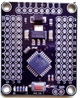
Anyway, this was a golden opportunity to do a little more work on my NANO peripheral. Oh you know that new NANO board I referred to elsewhere? with 3 pins per chip pin. Well, it turns out that they are not just 3 connections to each pin, but a ground rail and power rail – MUCH better. I should have realised that when I saw G V S on the board…
So one of the nice things about my ESP software is that the RGB fades from one colour to another rather than an abrupt change.. so I’ve now added that to the Nano “i2c peripheral” – just a simple comparison of values, I’ve not done the whole floating point percentage thing – but it works well enough.
I’ll give you an example of the MQTT command from my ESP board to the peripheral for a 12v RGB LED set..
{i2c:9,0,12,6,255;i2c:9,0,12,9,255;i2c:9,0,12,5,0}
Looks complicated but it is three separate commands, one for each LED. So the command is “i2c” – I’m talking to device 9, no return values, the command in each case is 12, followed by the pin and the value for that pin. Simples.
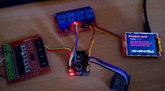
So now by the time I get this mounted up outside I have a nice display run by the ESP board – and 4 relays and 4 high power PWM controls on the peripheral – not to mention a DHT22 on the ESP – and 4 analog inputs again on the peripheral – lastly, some dividers on a little bit of breadboard so they’ll handle 30v inputs (solar input, battery voltage, output voltage and output after a buck regulators to the LEDs etc). Here’s a link to the current “peripheral” code.

