A short while ago I put together a little poor-person’s signal generator (or signal generator for people who only use them once a year). It is currently waiting for me to drill a tiny box to put it in. Meanwhile of course I’ve taken possession of a FeelTech function generator which does the same and more (albeit at a higher price).
All of that is very nice but the frequencies coming out of these things are no good for experimenting with microprocessors which might need 16MHz or much higher.
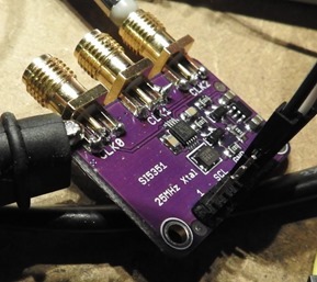
And so it was that a kind blog reader pointed me to the SI5351 clock generator board on AliExpress. This little beast claims to have 3 separate outputs able to handle 8KHz to 160MHz.
So, yesterday the board turned up. It comes unsoldered and requires that you solder a 7 way connector and 3 output connectors. The former was easy, but as you can see by the mess of soldering, the output connectors are not trivial to solder on a tiny iron made for SMT work due to their bulk efficiently taking the heat away – I simply could not get enough heat in there to do a visually great job.
However, functionally the soldering was just fine so I went off in search of a test library for Arduino (always a good starting point) – of course there’s an Adafruit library but after taking a quick glance I decided you had to be a ham radio fan to get your head around the setup – and so instead went for this library.
Of the 7 connections you need only 4 i.e. ground, power, SDA and SCL (I2c). I hooked these up onto a board (with 2k2 pull-up resistors) – all running on 5v. I ran the library and, well, it just works.
If you study the library there are a number of options – I chose to ignore them and go with the easy option.
#include “si5351.h”
#include “Wire.h”
Si5351 si5351;
void setup()
{
// Initialize the Si5351si5351.init(SI5351_CRYSTAL_LOAD_8PF, 0, 0);
si5351.set_freq(810000ULL, SI5351_CLK0);
si5351.set_freq(820000ULL, SI5351_CLK1);
si5351.set_freq(830000ULL, SI5351_CLK2);si5351.output_enable(SI5351_CLK2, 0); // turn off output 2
}
In the above example – output 0 is set to 81KHz, 1 is set to 82KHz and 2 is set to 83KHz – and output 2 is turned off.
It really is that simple – I found contrary to the advert that I could go down to 4KHz and as far as I can tell everything was working just fine at 160MHz – but my scope coughed up it’s lungs at anything over 120MHz.
The frequency values are shown to a resolution of 0.01Hz. If you want to use Hz just divide by 100.
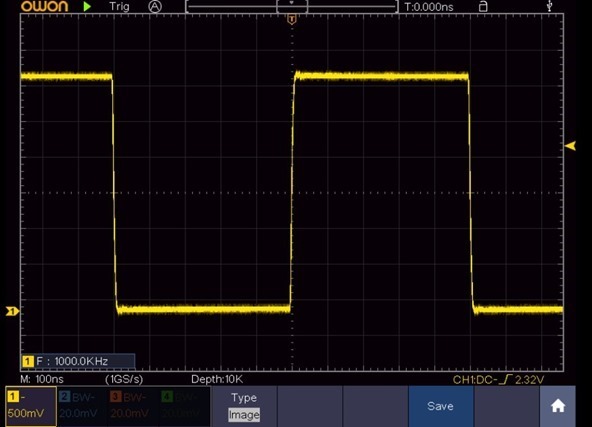
Here’s the output when set to 1MHz.
If you look at my function generator code where I put the settings onto an SSD1306 display and had setting buttons and memories – it would take no time at all to modify that code to make this into a neat little clock generator unit.
Now I just need some nuts and plugs for those small connectors… ideas anyone – I need nuts for them (front panel) and male connectors ???


Hi Pete
Thanks for sharing this excellent blog.
I guess you need a SMA male connector like an adapter SMA male to BNC female if you already have such cables at home. I personally prefer cables with the BNC serie. They are easy to work with.
Anyway something like this?
https://www.banggood.com/4pcs-BNC-Male-Plug-To-SMA-Female-Jack-Straight-RF-Connector-Adapter-p-1050143.html?rmmds=buy&cur_warehouse=UK
One more thing: kilo should be abbreviated with “k” lowercase and hertz with “H” uppercase like 8 kHz or 25 MHz 🙂
Thanks for that.
don’t know what soldering iron you have, but i took these tips a while ago, and the 45° one is very good for this kind of soldering: https://it.aliexpress.com/item/THGS-10-Tip-Set-Tips-Soldering-Tip-Set-for-Soldering-Iron-900-T-I-BK-1/32748579123.html
Mine are too small, I need as you say a 45 degree tip.
Pete, the ‘this library’ above seems to be missing a link. Is that correct?
Fixed, thank you.