
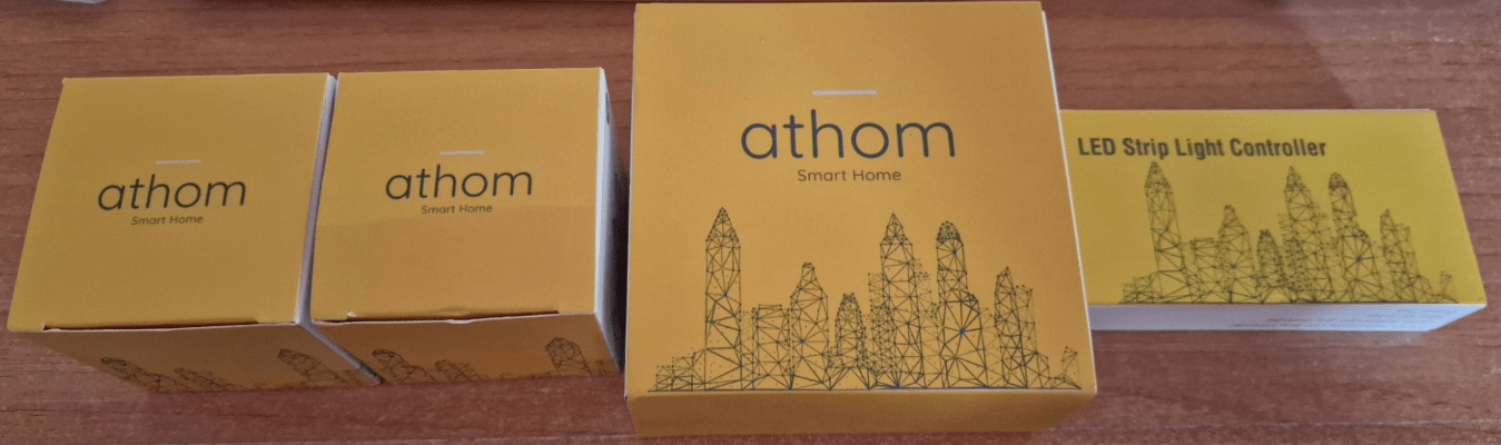
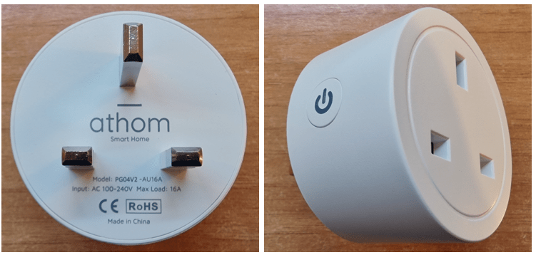
I always get excited when a package arrives from Athom (2025 now branded as IoTorero) Last time it was various ESP-HOME-compatible lamps and I’d previously had some Tasmota-pre-programmed bulbs from them – which now light up my living room and office. I’m not so familiar however with their general smart-home products, hence I was excited to receive a couple of their model PG04V2-AU 16A UK smart plugs (I got that from the back of the plug – the pretty box was a bit vague on details other than to say the plugs are 2.4G WiFi).
Indeed at this point I’ve NO idea what’s inside them… Oh, except that the instructions state “Tasmota” – that’s a good start.
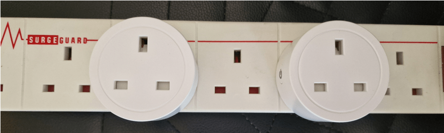
So, straight out of the box I plugged one of these into the mains here in Spain, in a UK extension – actually I plugged two in and was a tad disappointed to find that despite their small size I could still not fit two side by side – just a couple of mm smaller and they’d have nailed it… that and putting the on-off control on the top, not the side. Of course I’m assuming that all of my UK extensions have the same spacing here – I could be wrong. I always seem, with Smart Plugs, ending up every other available socket empty.
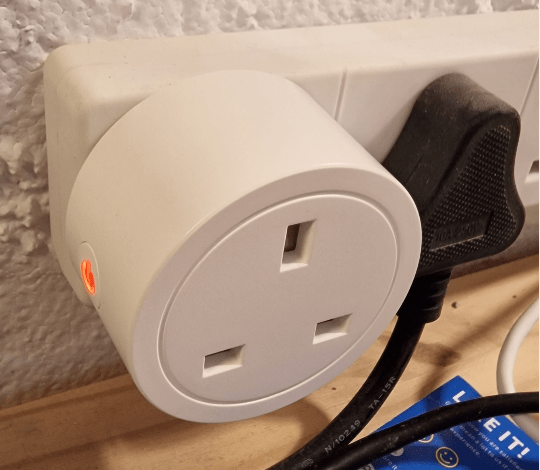
Ok, got one plugged into the wall and a normal plug right next to it – that’ll do me (see right). There’s a light on the (left) side button alternating 0.5 secs each way) purple and red – very pretty… I’m guessing at this point, all I have to do is have my phone find a WiFi access point starting in “Tasmota…”
Correct – so my Android phone (I could have used my PC or an Apple phone) sees the access point…and from memory if I point my web browser at 192.168.4.1 (the webUI or web-page user interface) – YEP – up pops the web page.
Time to fill in the details of one of my 2.4Ghz (not 5Ghz) WiFi access points (i.e. SSID and password). Done. My phone connects back to the normal WiFi SSID but not before telling me the address of the Tasmota’d plug on the network (below right in blue).

Sure enough – at this point I could just stop – but being Tasmota firmware-driven – I can now find that IP address on my network and do things like change the name of the smart plug, add an MQTT link and all the other things you can do with Tasmota with ease.
So now, my PC browser, pointing at the address above-right – shows me the Tasmota control panel for that switch and I go into configuration and change the name to “uk-athom-1” (my choice) then under “configuration – other” make the name and friendly name “uk-athom-1”.
That just leaves me two things to do – add in the MQTT credentials and address for my home control (this may not be needed if you just want to use the webUI to control the plug) and as I always do (some day I’ll regret this) – update the firmware (I don’t recommend the latter unless you’re familiar with Tasmota firmware updates – it’s trivial to do but there’s always the chance of messing up)..
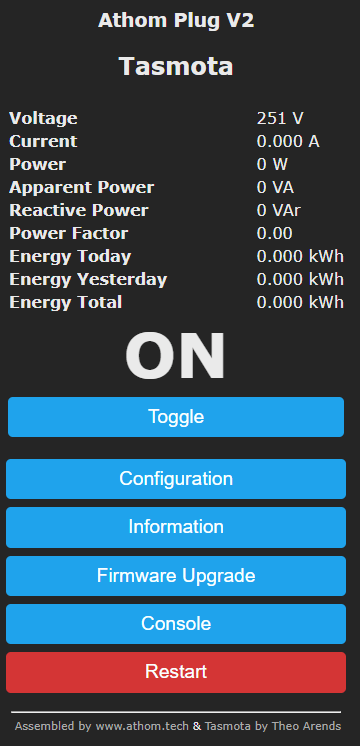
Well, it all worked. I’m happy. And I’d not quite twigged but these smart plugs are not only 16A but are power-monitoring as well. That view just below shows my new socket in one of my favourite tools on the PC for Tasmota – TDM – Tasmota Device Manager – alongside a couple of other Tasmota-driven smart sockets (I converted the others the hard way – I could be wrong but I’m only aware of Athom who pre-Tasmota the hardware).


And as if my magic – the new plug, having retained all it’s settings – is now running the latest version of Tasmota (the development version in my case – on September 23, 2022 being v12.1.1.2). I’m happy. If you’ve gotten this far, I assume you know all about the free, open-source firmware Tasmota – so good that some time ago I stopped developing my own ESP8266 firmware – talking of which – as indicated in the Tasmota INFORMATION page, these switches are indeed running ESP8266EX chips (with 2MB of available FLASH), proving there is life in the old dog yet – indeed lots of the controllers which I use, utilize the ESP8266 chip – thankfully I didn’t have to open up the plug to check this as it is all detailed in the INFORMATION panel.
All this time, the red light on the side switch was on – I hit TOGGLE on the web interface and sure enough, the light went off.
And finally for this section on the new Athom plugs, I plugged in my wife’s hair drier, turned it on – and quite quickly..
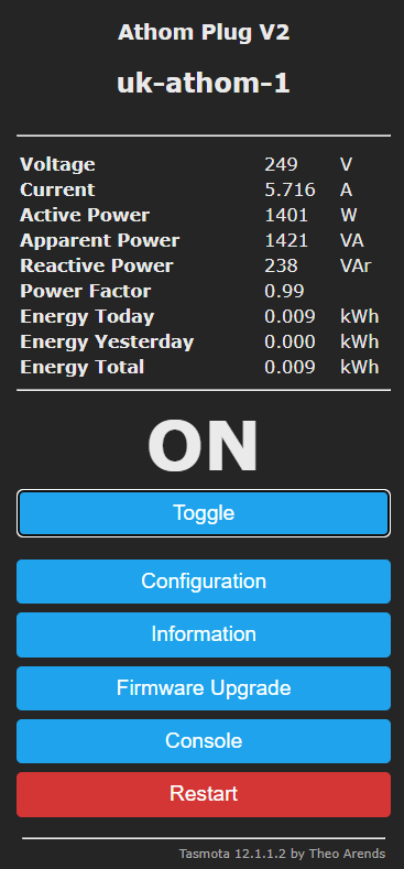
You can see in the photo on the right, the voltage, power consumption, amps and overall energy used today..
I’m assuming the power monitoring will have been set up accurately as, at least according to Athom’s AliExpress ad, the built-in HLW8032 consumption monitoring chipset needs NO calibration. That’s a plus. Rather than give AliExpress an easy plug, I’ll point you here directly to Athom’s website.
Next I’ll check out the no-neutral mains light wall switch that arrived, along with the LED light strip controller (the latter comes with leads and a screwdriver, works on 5-24v and has a maximum of 16A output) – but first – some shopping. The controller, unlike those I’ve tackled before, handles Serial RGB strip of the power, ground and serial variety as well as those with separate clock and data. More on this later. I hope you enjoyed the above info on the Athom smart plugs.
One last thing, I went into configuration – other and ticked “emulation – belkin WeMo” – looks like “uk-athom-1” wasn’t the best choice of names…. so in “friendly name” I’m now trying “my spare plug”.
THAT WORKED!! “Alexa, turn on my spare plug”.
The Second Day – Second Smart Plug
I got up early this morning and decided to push my luck with the second Athom plug. I called this one “uk-athom-2” and “my-other-spare-plug” for Alexa, repeating the same procedure. On a quick search, Alexa said: “I found ‘my other spare plug’ and you can control it by saying ‘turn on ‘my other spare plug'”.
For reference, by default, built into the Tasmota upgrade page is this address and if you are upgrading any device, I’d suggest leaving that as-is for the safest Alexa experience. However I like to go in at the deep end and miss out the “release” folder hence obtaining the latest nightly build. Clicking on the above links (if you are on a PC) will download the Tasmota file in each case to your download folder – it’s that simple.
Perfect. Time for the upgrade again. This time, no upgrade. As you can see below, the device remained stubbornly at version 10.1.0 (nothing wrong with that but I like to be up-to-date). I waited a couple of minutes and the device re-appeared on my network – still with the original build of 10.1.0.

It just so happened that last week I was having issues updating an unrelated file and from the same Tasmota address I’d grabbed the file tasmota-minimal.bin.gz to try the 2-part upgrade, starting with the minimal file then the full tasmota.bin.gz
Around 3-4 minutes after grabbing the minimal file and setting it off using the “upgrade by file upload” method in “firmware upgrade” I was beginning to wonder if I had a problem when up popped this in my Chrome browser (see image below left)…

So far, so good – but I’ve found with some devices it pays to be very patient with Tasmota upgrades – no actual work is involved but don’t do this if you are planning a trip out in the next 10 minutes. I ran the full upgrade again and within another couple of minutes, magically, I had a fully upgraded device.
Of course none of this upgrade procedure is necessary – just my choice – the plugs will work with merely the initial WiFi setup – that’s all. If you don’t want Alexa compatibility, MQTT compatibility or the latest firmware you can simply do the first step and that’s it. Note that the full upgrade again took me to Tasmota version 12.1.1.2
There’s a lot more you can do with Tasmota on these and similar devices of course: you can toggle the output on and off in the webUI, set up to 16 timers including sunrise and sunset, set up Tasmota to run with Domoticz, oh, and we should not forget the console, there are a ton of useful flags that can be set from the console as well as setting the timezone and so much more but you’d need to consult this (very large) Tasmota commands page for more on the subject. Tasmota is SIMPLE to use in one sense and VERY comprehensive in another. For the purposes of our power-monitoring Athom plug, the default settings are generally ok.
Next: The DS-101JL No-Neutral WiFi Smart Wall Switch
Where the smart plug requires no skills or qualifications other than a modicum of common sense, the wall switch on the other hand (this is the point where people usually use the word “qualified” – I won’t as I’m not qualified and have been house wiring my entire life so I’d rather not be hypocritical) the wall switch not only requires the kind of skills that you might find in an electrician but also some common sense and given the instructions below – a spot of lateral thinking.
The switch can be wired with or without using the NEUTRAL wire (bear in mind that, though the concept of live and neutral is common throughout much of the world, here in rural Spain, much of the time there appear to be just two wires with no particular attribute for each (no really, I’ve seen just 2 black wires behind a switch or coming out of our wall to a light bulb etc.). Ok, so generally the idea is that a small capacitor (with high value discharge resistor built-in) builds up enough charge to power the switch in the absense of a neutral connection. A suitable capacitor is supplied with the Athom wall switch. Other than this – Tasmota WiFi setup is the same as other Athom products such as the smart plugs described above.

Below are the instructions which came with the switch – and also there’s a photo of the box underside.

and the flip side…

and the box…

and onto the switch front panel:
Yes, in order to set up the switch, I plugged the L and N connectors into a 2-pin mains lead in no particular order and yes, once plugged into mains power, the centre light below was on permanently and the blue WiFi light below was flashing rapidly. In the instruction image above you’ll see N, L, L1, L2, L3 and L4 connectors – in fact in my switch there were only N, L and L1 actually fitted.

Ok, onto the Tasmota setup – as predicted, setup was as above. I initially set my phone WIFI off looking for a new access point beginning with tasmota – and followed by some numbers and characters – found straight away. Again I set my phone to use that access point and again pointed my web browser at address 192.168.4.1
The setup page was found immediately and looked exactly like the one that appeared when setting up my smart plugs.
The WiFi light on the switch became solid blue for a few seconds then went off. A web page appeared on my phone at the predicted address. “Athom 1Gang Switch”.

I won’t go deeply into the rest of the setup as it is identical to the smart plug setup above.
When all done, all you have to do is wire up as per their instructions above bearing in my safety precautions – and if you don’t feel insulted by being told this, you maybe should not be attempting to wire up a wall socket.
Before disconnecting the switch so it would be ready to try it with a lamp and the capacitor in a no-neutral setup (or in my case simply one-power-line-to-the-switch setup), I performed the same prodecures as for the smart switches and as I only have one of the wall switches, that made choice of name very simple indeed.
Of course, the friendly name for Alexa can contain spaces, the hostname and device name (I’ve never figured out why there are two entries as they always end up identical) should contain no spaces, as should any mqtt topic as far as I know.

Before disconnecting, I touched the blue circle in the middle of the front panel – the light went out immediately (off), the relay toggled (in this case to OFF) and the blue WiFi light flashed briefly.
Ok it’s all making sense now, as this is 220-240vAC we’re talking about, the capacitor IS providing a tiny amount of electricity to the switch in the absense of a return power connection. Easy.
I utilised the “neutral wire” for both setup then for actual operation,. See below – the centre circle lights up when the bulb is on (personally I’d rather have had it the other way around to help find the switch in the dark but see later.

Note above – neutral in the corner (N) connector plus one wire from the lamp. Live in the second (L) connector – lamp in the third (L1) connector. In this instance I refer to live and neutral but my mains lead is simply connected to a reversable 2-pin mains plug at the other end. I used a 7w LED bulb I happened to have handy – and red and black wire that is really not meant for 220v use – don’t copy that. Of course, all wiring was carefully done with the mains power plug disconnected.

I checked that I could turn the light on and off both from the button AND from the webUI page. No problem (I already know that in these circumstances I can turn the light on and off from MQTT in my Node-Red installation).
OK, I went into the Tasmota “configuration – configure template” option in the webUI and changed led_i to led – reversing the operation of the centre LED. That at least works in the neutral-included version. Question is will it work in the alternative version with no neutral?

Interesting – in the new setup complete with capacitor – I noted a VERY brief flick of the light when I first applied power to the mains plug. So – original setup – lamp off – no indicator – works perfectly – now back to my experiment at reversing the LED indicator setting.. YEP – that works TOO. I LIKE IT. Note below, the light is ON and the centre indicator is OFF – makes more sense to me. The operation of the WiFi LED is probably reversible but that’s just being silly.

I have to say that although the two fixing screws are provided and the centres are the same as an existing wall metalk insert, the actual socket backing is slightly bigger than my standard Spanish backing fitting will allow. Presumably the version I received was, like the smart plugs, for the UK market.

I’ll cover the LED STRIP controller later.
The Point of Tasmota?

If you’re not familiar with Tasmota, you may be wondering what’s so special about devices pre-programmed with it? Well, it’s free, actively supported and does NOT require connection to an external server. Genuinely, no catches.
I use Tasmota to give my devices MQTT capability so I can control them from Node-Red on my Raspberry Pi which remains turned on 24-7 – but depending on your needs, there’s another way – a relatively new and up-and-coming package called TASMOTA-REMOTA is available for Android only.
Here it is in action – it took me seconds to set it up to handle my new ATHOM wall plugs.
Including the power measurement on that page is of course optional. As you can see, one of the plugs is ON and simply pushing the gren “button” will turn it off and vice-versa and the package is quite versatile and again actively supported. I have no axe to grind either way on this package – I’m just bringing it to your attention as I like it and have found the author to be helpful.
As things stand I don’t see how Tasmota Remota could be used via my favourite per-device VPN for external use but that’s another matter and that’s why we have the likes of Node-Red-Dashboard and a miriad of other phone interfaces and dashboards.
Finally the Athom LED Strip Light Controller
You may ask, how can a LED strip controller be interesting? Well, regular readers will know that I’m well familiar with the generic Chinese H801 controller which is handly for RGB and RGBW LED strip – especially after you;ve freed it from it’s built-in code and flashed it with Tasmota. I’ve used that on 12v and 24v RGB strip as it takes in anything from 5v to 24v.

What I’ve not had, other than home-made affairs, looks like a similar unit for serial 5v RGB LED strips – but there the similarity ends and it’s an eye-opener. NOT kitted out with Tasmota, but pre-flashed with WLED, the handy Athom LED Strip controler handles a range of serial LED strips including 3-wire and 4-wire versions and… well, the photo will tell you the rest.
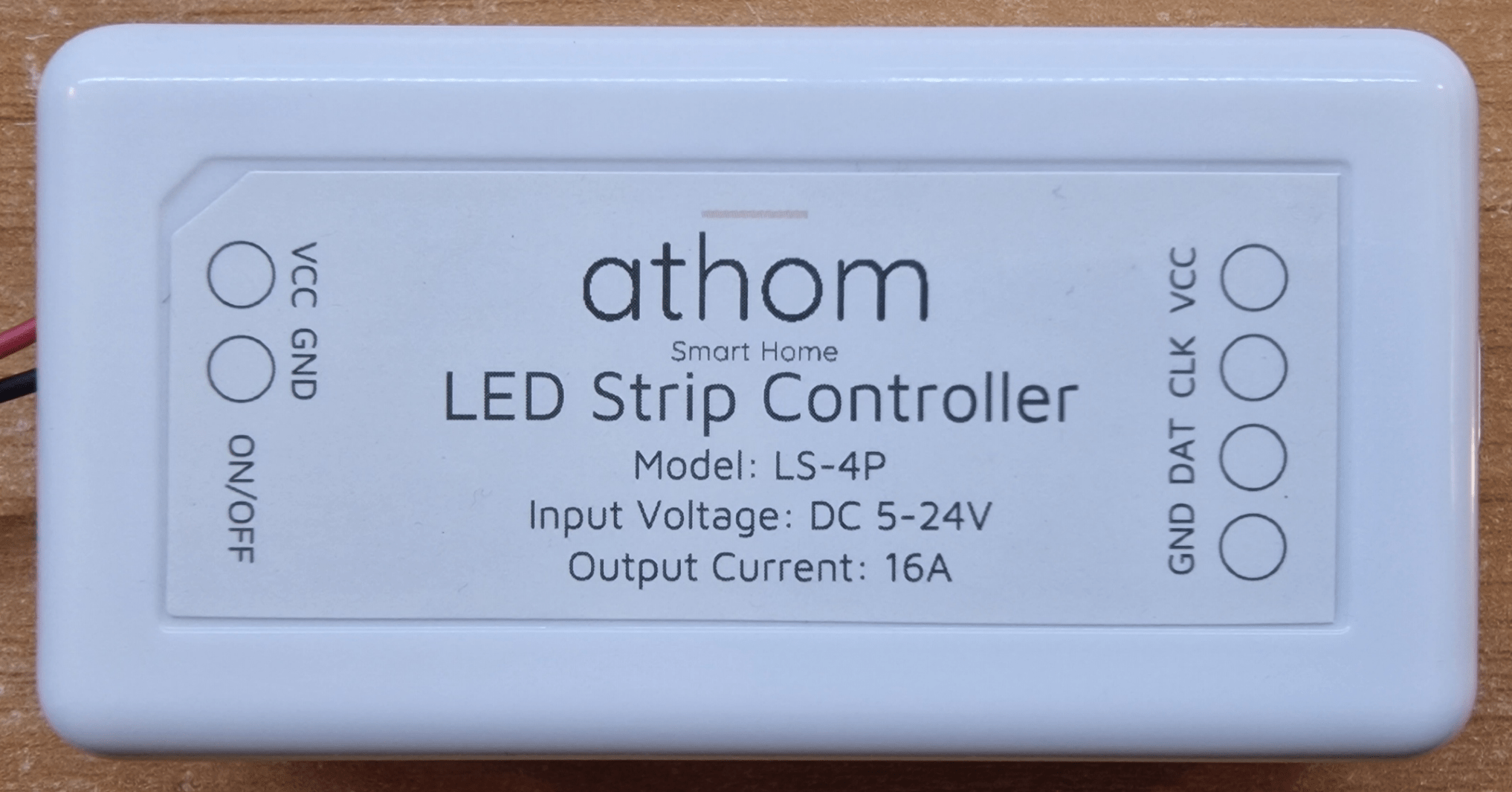
The Athom unit is far-more “end-user” as it has a friendly connection system, is pre-flashed with WLED and yet remains quite inexpensive. It used the freely available WLED APP or indeed generic PC web interface. I’ve copied the spec from the Athom website – there is lots of good info there and a lot more on the WLED website. Why do they have a relay? No idea…
Input: 5V-12V
Max Load: 16 A
16A Relay Switch
Strip support: WS2812B WS2811 WS2813 WS2815 SK6812 TM1814 APA102 WS2801 LDP8806 GS8208
Not having a clue what to expect, I plugged a 5vDC supply into the unit, plugged in some WS2812B strip, taking the middle signal wire to the CLK input…. now what?
AHAH. I opened the WiFi settings on my phone and up popped WLED_D9D379. The phone went onto the access point and up popped a WLED interface – no APP needed… just a web page…”Welcome to WLED” it said and invited me to either go to WIFI SETTINGS or TO THE CONTROLS. Nothing – looks like I picked the wrong input. DAT – thinking about it, that makes more sense.
I went off to the Athom site to look at comments “The controller is not much powerful due to the use of ESP8266, but in simple scenarios can be used” – this fellow needs to get out more (actually I think he has it in for Athom – repeated remarks on their site – maybe he has his own competing product)… the ESP8266 is MORE than able to handle a shedload of LEDs using WLED IMHO.
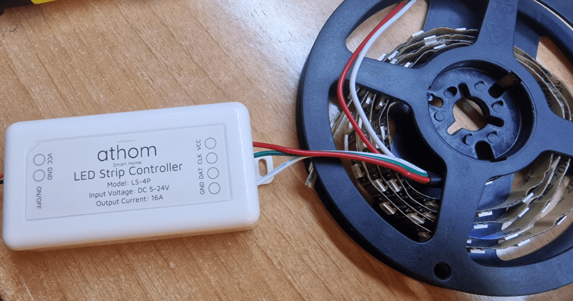

To cut a long story short, I hooked up ground and signal the wrong way, and used signal OUT on the strip instead of signal IN at the other end. Well, no harm done – all working now.. 3 wires, ground, DAT and VCC… done.
Oh, I see the point of having a relay – so that idiots like me can get the wiring all wrong without doing any harm. While I worried about that, I set up the unit to use my 2.4Ghz WiFi access point – using the web interface on my PC – NOW I could complete the job on my PC.
The power of WLED is way beyond the scope of this intro to the Athom unit – it REALLY is powerful – and you can sync multiple LED strips together, produce fabulous patterns – my all time favourite effect is shown elsewhere on the blog – rainbow…
The WLED software defaulted to 30 LEDs – I noticed my strip had 64 LEDs – a quick menu setting later, take off the brightness limiter and…

I could be some time on this – but I suggest you simply take a look at the WLED site – I could spend DAYS messing with this stuff and the Athom unit makes it all so easy – I need MORE of them. As for the Athom unit – can’t fault it up to now. And tro save you looking it up – here are the hardware assignments – Button(GPIO0), Relay(GPIO12), Data(GPIO1), DCLK(PGIO3)
I DO wish Microsoft Phone Link would copy videos and not just photos – but then I remembered CLIPT – on my phone and PC – copied the video below no problem. I then sent off the short video to YouTube and here it is – warts and all.
The onboard 16A relay only turns the LED drivers on and off, as when it is off, you can still turn the unit on and off with the web interface.
Here’s a final thought for the really ambitious/tight – if you’re using WS2812B strip – the WLED package is actually able to handle up to 3 instances of LED strip – and that CLK output is not being used here. Not investigated but it might just be a tweak. https://kno.wled.ge/features/multi-strip/
My unit came complete with WLED v1.13.0-b6 firmware, the current software for those who like to meddle is 1.13.3. I (blindly) tried the update from the releases page – 1.13.3 – downloaded the ESP8266 file to my PC downloads folder, went to (in my case) http://wled-wled.lan/update and started the OTA update.

RIGHT – this is very important – after the upgrade failed (not doing any harm) I contacted tech support at ATHOM and:
Hi
Use the firmware from the link below
https://github.com/Aircoookie/WLED/releases/download/v0.13.3/WLED_0.13.3_ESP02.bin
I’d used the wrong link. This one worked and my Athom unit is now BANG up to date. They THEN followed that up with another useful link:
https://kno.wled.ge/basics/install-binary/#what-binary-should-i-use
Can’t really ask for more – on a SUNDAY no less. Try getting support like that out of a bank (or pretty much any other large organisation).
Finally, let’s not forget that WLED supports analog CLOCK mode if you happen to have a 60-LED ring handy. It’s all in the WLED config settings and the software can look up a time server to make sure it is showing the correct time no matter where you are.
Approaching 2023 it’s now so difficult to find a decent smart plug, flashable with Tasmota. Athom is a good option, being 16A and power monitoring, but why oh why do they make these in this oversize round format?! I’ve some great compact rectangular (49mm wide) units that can be installed side by side. Sadly these are no longer available. Wish I’d have bought more back then…
Yes I agree. Almost all smart plugs are too big to fit side by side in an EU or UK extension. More on Athom when I fix a strange issue with my WiFi. They just sent me their Zigbee Gateway (in a case).
May 2025 update: I STILL wish more people would make smart sockets – preferably narrow ones – which use ESP32 and can be flashed with TASMOTA. If nothing else, the rules and various options in Tasmota make it FAR better to use than most smartplugs without Tasmota. I just updated one of my Tasmota’d smartplugs to erboot my incoming 5G router when there is no response from Google. It does this all on it’s own without Internet or even LAN working as it’s using rules within Tasmota itself… I’ve published that in the blog for anyone interested. https://tech.scargill.net/a-tasmota-zigbee2mqtt-learning-day/
I have 6 of these Athom plugs (AU-NZ version though) and one of them after about a month of impeccable service one night just gave up – it shows on the network, it reacts to the commands, it measures power consumption, it even clicks when toggling, but…it stays always ON, doesn’t matter what state is indicated – seems that relay contacts just gave up and are stuck together – simply welded. Load it was operating is near 11A (2500W) charger. Of course I did disassembled the case (it holds together with some minimal amount of superglue I guess as just going with the nail around the enclosure was enough to crack it) and found that relay it utilises is Y32F-SS-105LMH by YUANZE ELECTRIC (indicated as 16A 250VAC) and first things first checked the AliExpress for the availability – no luck. Next – just a general search on Google – no luck as well – only 10A versions available. Hmm, thought maybe it’s not genuine marking and Athom plays some dirty games – no, everything is fine, checked YUANZE web page – they do have that 16A version on their products page – just not available to purchase anywhere else. OK, will wait for some time and hope it will become available some time soon on Ali – luckily I do have some spare one (used it on the new fridge to check energy consumption) so did fast backup of the settings on old one and uploaded it to the new one. Everything worked flawlessly and it wasn’t any need even to change an IP address – all details was perfectly transferred to replace the dead one (as I am using it with MQTT and Node-red, as well as summer / winter Day time savings. In general very happy with Athom plugs, more than Pre Flashed TASMOTA WiFi BR30 Smart Bulbs 12W, as these ones did not keep set colours when dimmed to some level (was planning to use them as an artificial sunrise, but somehow it’s dirty greenish before getting to orange/red’ish 🙂 – still nice to have as a night lights, but not perfect to the purpose I bought them. Hope it helps some guys to know limitations
Thanks for that Aidas
I normally caution in my blog about going anywhere near the maximum current on these relay-driven devices – not just these – any. 2500w should have been OK unless the load was in any way inductive in which case personally I’d stay well below the maximum – exactly how far would be up to someone more into the science of inductive loads than myself… but in several years of using a wide range of smart plugs and related I’ve only once managed to burn one out and that was while powering a 3KW water immersion heater. Do you want to comment about exactly what you were powering?
I generally use the Athom devices with Node-RED, MQTT and node-red-dashboard, in fact I’m using the 15W Athom pre-Tasmota’d bulbs and of all the (very many) smart bulbs I’ve tried they are amongst the most reliable and brightest. I had issues with their very early 7W RGBW bulb but since then no problems – I have four of them in the living room and in my office one 15w and two 7w – in use almost every day for much of the day – I can’t get on with variable sunlight when I’m working at the PC.
Of interest I’m just about to write-up one of their pre-programmed (serial from 5v to 24v) LED strip controllers – 16A max… strangely they’ve used a 16A relay in there despite the chip being able to turn all the LEDs off.. more on that when I get the unit wired up. This one isn’t pre-programmed with Tasmota – it’s WLED (which I’m already well familiar with).
Thanks again for the feedback.
That 2500W load is battery charger (50V, 50A), using it to charge 4 batteries from the Tesla S. And it’s rather smart charger, measuring voltages before starting to charge, starting with small current and gradually increasing it to the max 50A. My guess that Athom plug gave up on the disconnect moment as it should handle almost 11A @ 240V. Most probably will replace it with POW2 from Sonoff or maybe even with WIFI Circuit Breaker by Tongou (from AliExpress) as it’s rated up to 63A, although requires case to be opened and ESP reflashed using USB UART adapter. See attached photos of Athom & Sonoff POW2 relay size as well as Circuit Breaker (OK, not possible to attach second photo to the comment, but it should be easy enough to find that circuit breaker on Ali).
Re LED Bulbs – yes, you are absolutely right, on the bright size they are impressively bright and white colour temperatures adjusts nicely, just on the dim side isn’t perfect. By the way, I’ve split white and RGB channels (by using SetOption37 128) and now I am able to control RGB and white brightness and colours independently.
On very heavy duty stuff, I too have been known to use a Sonoff to drive a breaker. Cheap enough.
My problem with ALL RGB lights is, though I know our eyes have red, green and blue sensors – hence RGB really ARE the primary colours as it were… imperfections in the LEDs mean you rarely ever get a decent yellow out of red and green – LED strip being a prime example.