Page 2 – And now, my Banggood 4-Way Relay Board
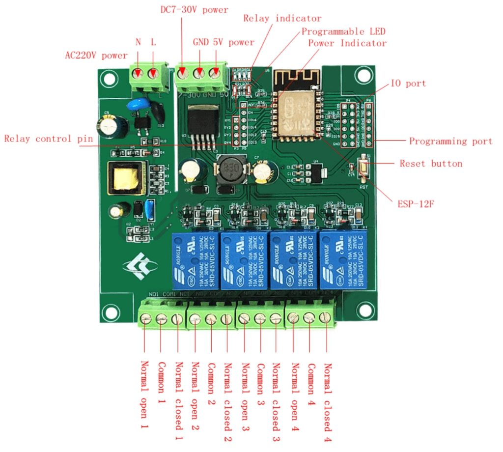
The interesting thing here is – had timing been different, I might have gone down a different route – as a new board from Banggood has just arrived for me – resembling the board I mentioned above which Aidan and I put together some time ago but never took into production (but with 4 relays instead of 1).
This board however goes a stage further and offers not only 220vAC input, but also 7-30v DC and 5V input. It has 4 10A relays and connectors for spare GPIO and FTDI – which makes programming it up for Tasmota a snap. So, kind of like the Sonoff 4CH Pro but cheaper and more flexible but uncased.
Depending where you live, this board should land on your doorstep at under $10 (€8.70 inc shipping to Spain). For a general purpose ESP8266 board it takes some beating, depending on your requirements (if you are simply driving 12v LEDS then the H801 might be a better bet – but for say 4 completely separate mains devices and some input sensor(s), this is a better idea. GREAT for experimenting.
I had to use an FTDI once for set up but after that I realised I could possibly then make use of the RX and TX lines for even more extras – updating Tasmota as usual via OTA.
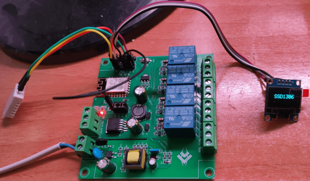
The manual on the Banggood site mentions some arduino code – but given the vast peripheral support of Tasmota – why? Mine’s getting a blue OLED display (GPIO4 and 2) and a DHT22 on GPIO5 unless I can re-use a serial pin!! What fun.

Having set up the Tasmota configuration so that GPIO16,14,12 and 13 were attached to relay 1,2,3 and 4 respectively – and having put in the 4 board links associated with those relays (to the left of the ESP8266), not only did the relays toggle on and off, but 4 onboard LEDs (top of the board, to the left of the ESP8266) started following the relay status.
At this point – a working board. However there would be no reason to stop there. I used “tasmota-display.bin.gz” as that obviously gives access to relays etc. while providing maximum flexibility for any display one may care to add not to mention the odd sensor.
There is an uncommitted (inverted) LED on the board so for now I’ve attached GPIO5 to that and used GPIO4 and GPIO2 for i2c so I could put a 1.3″ SSH1106 OLED board on as well – just because I can.
Note: the dev version of Tasmota – 9.3.0.1 was brand-spanking new at the time of writing. Bit of an odd issue late on Friday night (Feb 19, 2021) – the SSD1306 was working and then stopped. The SSH1106 would not work at all. By late afternoon Feb 21, 2021 this was all magically fixed with no version renumbering.
HERE’S THE WEIRD THING. using the standard defined outputs for the relays originally, I had noticed that on power up, one of the relays flickered briefly (before and after I started messing with the SSD1306). In the process of setting up the board from scratch – I decided to set up i2c FIRST by OTA (not FTDI) – nothing worked – until I realised the board had reset it’s hostname to – would you believe “WEMOS-D1-MINI” – don’t look at me! So I set it back to “relay4” and with my display now working (after doing nothing more than setting up i2c and turning the auto-created power ON in the console) the display lit up with “SSD1306”. I immediately felt the urge to experiment.
displaytext [zf1]Hello there
Yup, that worked… z here means clear screen and f1 changes the font – yes, it’s that easy.
Now I was on a roll, I wondered, getting rid of the relay flicker, could it be as easy as no longer using GPIO16 ? YES, so I set up 3 relays using the same ports as before but GPIO15 instead of GPIO16 for the last one and inserting links accordingly. There’s a nice board indicator – could that be made to use GPIO16 set as an inverted relay 5 ( as if it would matter if that flickered on power up?). NO – as there is no status info available from GPIO16, I tried GPIO5 – that worked.
With just that perseverance I now have a 4-relay board who’s first relay works better than it did at launch…. ie no relay chatter on relay 1 at power up) – and I can also run I2c, for example an SSD1306 display – and still have an IO pin (GPIO3 (RX)) with which to attach a DHT22 – which I just did for the sake of it. What fun!
Final mod – GPIO3 (RX) to the DHT22, freeing up GPIO5 for an onboard light (relay_i 5).
Who says the ESP8266 doesn’t have enough pins. So, in the image above, toggles 1 to 4 control the relays – toggle 5 (power 5) turns the internal LED on and off and toggle 6 turns the SSD1306 display on and off.
This link will take you back to page 1 – the H801 Controller.


Does anyone have the schematics oft the H801?
Better price on aliexpress: https://www.aliexpress.com/item/1005001651180110.html
Not when you take into account shipping cost. In addition Aliexpress now insist on adding VAT on all orders (at least to the UK) which brings up considerably more than Banggood. Have to say I’m impressed with this unit, good separation with surge and current inrush protection on the mains side. Does pretty much everything a 4Chan Pro does at a fraction of the price once I print up a case for it.
AliExpress often look like they have better pricing and sometimes they do – but first looks can be deceiving – indeed I think they often go out of their way to confuse the unwary and good look getting any support other than the automated “can you send a video of the problem”.
Also bear in mind that Banggood have lots of tech info on their website and no doubt more available on request.
I didn’t really mention the mains side of this unit. At least at first glance it is well designed, proper air gaps etc. – I like it.
ALSO since starting this reply I’ve updated the blog with some successes, suggest you re-read that last couple of paragraphs. This board has turned out to be a winner.