The Nitty-Gritty for those interested H801 Control
Ok, that was easy – now to actually run these things on an H801 controller – I’ve never used 24v on a cheap H801 controller before and up until yesterday, never run LEDs on 24v. PLUS I had forgotten the route to programming the H801 – thank goodness for the blog.
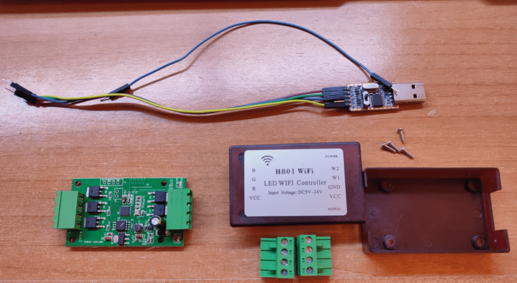
I opened up the H801 unit (simply pulled off the connectors, removed 4 screws on the underside and separated the top and bottom halves, the PCB dropped out).
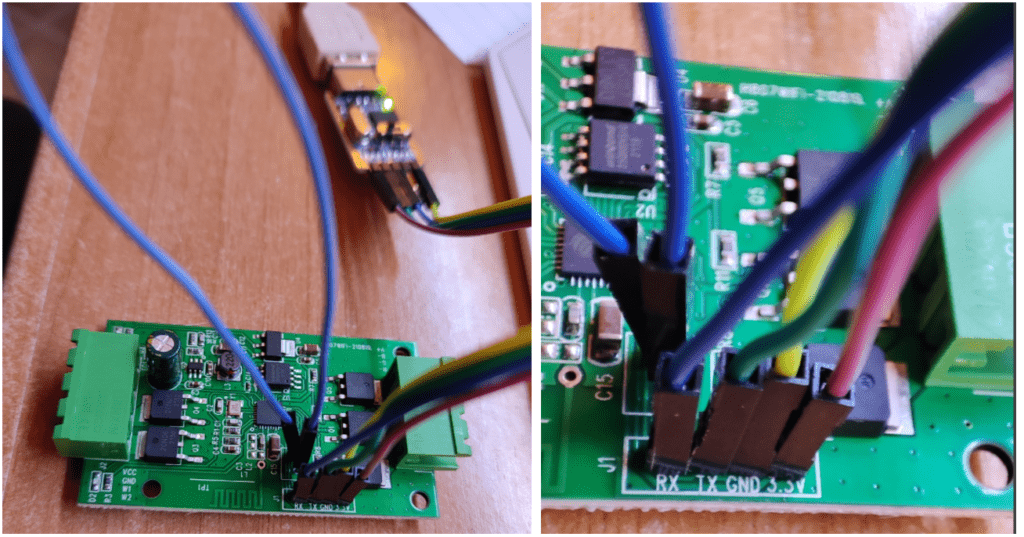
Next, I grabbed a simple FTDI I had lying around (available from China for €5 Euros max or you’ve been ripped) and hooked it to the PCB (pins simply pushed on) which involves shorting 2 link holes on the PCB again with wire with pins in it JUST for the process of FLASHING Tasmota – i.e. before applying power to the board and keeping the short until all done) – then….
The H801 board markings are a little odd when it comes to serial TX and RX so in this case I connected GND to GND, TX to TX. RX to RX, 3V3 to 3V3, but before doing ANY of that, ensured the 2 link holes had a wire across them (my blue wire above) as previously mentioned.
I then plugged my FTDI into USB to provide both signal and power for flashing (I do this on a PC, I’ve no experience with flashing Tasmota using other platforms than a PC and Windows – and in this case I’ve set the FTDI voltage link to 3v3 – not all FTDIs have links). The online Tasmota flashing software asked to ensure I had the right serial port… I always make sure there are no other serial devices connected when I do this (aside from mouse and keyboard).
Other than above, the flashing process is simple – tell the web-based software which Tasmota you want – I chose ESP8266 development version (I could just as easily gone for the release version but I like living dangerously).
The software connected to the board and flashed Tasmota – when done I disconnected the lot (including the link) and NOW put the H801 back together and merely applied 24v power and ground to the unit (5v-24v is good for H801 but the LEDs we’re looking at here need 24v) because at this point Tasmota is running with a local web server – no config.
I had my phone look for new WiFi access point and hook to said AP which the now customized H801 was providing… (starting with Tasmota and a dash then a number sequence – best to get past that point ASAP).
Now with my phone using that access point, a page opened in a browser on the phone at address 192.168.4.1 (always the same when putting Tasmota onto an ESP chip).
I was then asked to hook to a 2.4Ghz WiFi access point – I chose my nearest – “wififorus” and also gave it my AP password and hit SAVE.
At this point, the page said it was redirecting to the new device’s IP address – people including me sometimes miss this – it is important to make a note of whatever address that is, as the Tasmota access point has now shut down and the phone has most likely reverted back to normal WiFi use as hopefully) has the H801.
If I’d failed to make a note of the new address it might have gotten a little messy as you have to use a tool to find out which address on your network the device is attached to 🙂
I do the next step on the PC, not a phone – for ease. I opened a browser (I use Chrome) and went to the address I’d previously noted, at which point the new Tasmota interface popped up on my browser (at this point Tasmota knows nothing about the H801, just a generic ESP8266).
The NEXT step (this is a lot harder to write about than DO)… is to go to CONFIGURATION and set up some easy stuff. In CONFIGURATION, there are options to configure WIFI, configure MQTT and configure OTHER as well as actually setting up H801 configuration (or not). I do the first three, one after another (the board reboots after each) so that I can talk to the device via WiFi, via MQTT and also access it by a friendly name instead of an IP address.. but for now, the WIFI is set up (slight pause for mindless conversation on Facebook).
If I’ve missed anything out here you can check my original H801 blog entry here.. in particular I didn’t and don’t want a complex RGB light setup, just the basic PWM as this article is about the LEDs… so basically we’re looking at (in config) setting up a basic GENERIC (18) Tasmota setup with 5 PWM outputs (GPIO 4,12,13,14 and 15) to get 5 independent outputs which I can control by WiFi as PWM1, PWM2 etc with values 0-1023.
Endgame
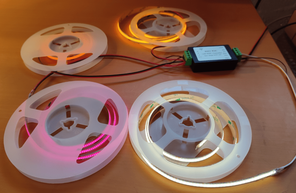
So now at the end of all of this, I had an H801 (called H801 on my WiFi for ease) talking to up to 5 LED STRIPS at 24v. All I needed was some bench room…check this out – warm white + cold white all in one strip – that’s novel… and of course I could have set up red, green and blue, but that’s boring when you can have orange, pink and yellow instead 🙂 I used the Tasmota SetOption (SO) 15 0 – ie SO15 to keep the outputs independent.
That gave me 5 outputs and I set these to a low value (range 0-1023 – I used 80) as I knew my thin PSU wire was simply not going to give 5 different outputs a fair chance at full power, not to mention my camera handling the brilliance. In the end I had to give COLD WHITE a higher value to give you the impression of both cold and warm white working together as one.
Of course, don’t get bogged down with this, there are a million ways to control LED strip – this is just how I choose to do it for simple lighting.
I’m not sure why, at low brilliance close-up, the pink in particular shows to both the camera and my eyes as individually discernable LEDs but trust me from over a metre away, NONE of that is apparent. You can probably just tell in the image above, bottom right, the adjascent warm and cold LEDs, again, only when you’re right next to the strip. I have to say this was the best free adventure I’ve had all week. I like the yellow, orange and pink particularly because of their purity compared to what you typically get when creating those colours out of RGB LEDs.
Ok, just one more totally unscientific check… brilliance of the RED compared to warm and cold white – again a slight change of colour balance in the photos which shows in the red. With both strips on full power and leads short enough not to cause issues, note left and right photos below… the rightmost of course has the COLD white.. and to the eye and my camera, in both cases, the red is quite bright by comparison, no doubt because the white LED only has half of it’s LEDs active at any time. I hope someone found this useful.


