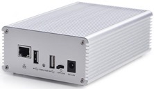
 I’ve separated this off as it has gained a life of it’s own. When I originally opened up the NAS box from FriendlyArm and plugged in my NEO2 (same company) I’d just planned on trying out the free NAS software. Little did I know how far this would develop…
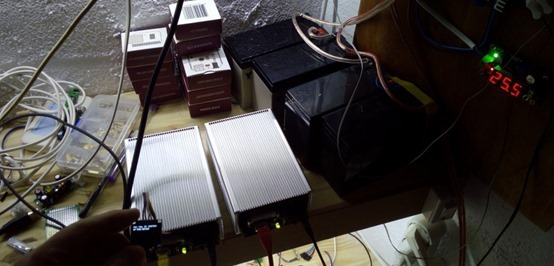
It occurred to me as I was wondering why on earth I needed a NAS without RAID in the first place, that this is a nice box with a nice power supply for a NEO2 and disk (I have the version of the box for the original NEO so a little filing of the ETHERNET opening was necessary – no big deal)…
The Disk:
So I put my SD with FriendlyArm’s Ubuntu into the NEO2 – along with my script for Node-Red etc etc, all set up and plugged in. As you might expect it started as normal so I went in to see if SDA (the hard disk) appeared.
Sure enough – along with SDA1 – so off I went to the web and found out how to use FDISK – deleted the partition, created a new one, made a directory in my PI directory and MOUNTed the disk. More on that later.
Well, I have to say that worked swimmingly well, so next using WinSCP I tried copying a 3.8GB file across. It copied flawlessly at 35MB/second!
So a couple of things – I’ve just finished my solar installation and I just happen to have 12v available from it – with lots of power to spare – I figured it made sense to plug this box in – ok, the network can still go down but there is NO chance of the 12v failing.
Of course you can’t access the GPIO pins via their connectors but the back is available so with a soldering iron I figured if need be I should be able to access a few of them given that there are schematics on the FriendlyArm site for just about everything so it would be no problem to out which ones are still free.
So I ended up with a disk (available via Samba once I remember how) and a nice sturdy box for my NEO2 and disk. As the NEO2 also has an audio in and out – it would be no problem with a drill to add a 3.5mm jack on the front panel. If I could think of a decent small socket for the job I’d bring the UARTs out too – remember – there are four of them – that back panel is sitting doing nothing…
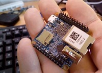 The next step was to allow the NEO2 to use the hard disk properly – i.e. instead of the SD. I’d already done a mount and tested a file transfer and achieved 38MB/s on a large (3GB) file – so I was happy to try.
The instructions are somewhat different to a Raspberry Pi due to this little machine not having a cmdline.txt file.
If you’ve used my script – absolutely make sure LOG2RAM is NOT running before doing this… best install without Log2ram. If Apache loses it’s log file in the setup, it won’t run – and that happened to me (mind you that is easily fixed).
Alternatively, if you already have it installed, disable log2ram (which is in my script for all my machines now but isn’t needed when using a hard drive).
sudo systemctl disable log2ram
then go to /etc/cron.hourly and delete the log2ram file – and reboot.
So the basic idea is to make a folder and point the hard disk to it – mount it – then copy almost everything to the hard disk… then change the settings in the boot folder to use the hard disk.
In this case – no changes to fstab – but one simple change to a file in the boot directory (boot.cmd) and having made the change you then you have to run a command to create a new boot.scr – this is not what you’d see for a Raspberry Pi.
This is what I did:
This can be done on a variety of systems.
Assuming a hard disk on /dev/sda and assuming for now being logged in as ROOT to ensure there are no issues with privileges…
I wiped any partitions in the drive (d, n, p, defaults then w for write) and created a new file system
fdisk /dev/sda
mkfs.ext4 /dev/sda1
I then rebooted. Some say you don’t need to – I found I did. Logged in as user ROOT I then made a directory called mymnt (for want of something better), mounted the disk over that folder (which now means that folder is actually on the hard drive and not the SD – simple when you get used to it) and copied everything across (excluding /boot and the /mymnt directory itself)
mount /dev/sda1 /mymnt
rsync -ax / /mymnt
At first this all seems odd but becomes second nature very quickly. You could add a progress option in there but the whole thing takes only a minute or two and I didn’t want to slow things down. The -a option means “archive”, which should preserve file permissions, modification times, etc., and the x option means “don’t cross filesystem boundaries”, so it’ll skip /boot and /mymnt
This can take several minutes as it has to copy the entire file system over. Good time to get coffee.
I then (while sitting in the /boot directory) altered /boot/boot.cmd 2nd last line.. changing the reference to the SD to the new hard drive – see bold.
setenv bootargs earlyprintk root=/dev/sda1 rootfstype=ext4 rw rootwait fsck.repair=${fsck.repair} panic=10 ${extra}
To make that work I had to run this line (again as root and this time sitting in the /boot directory)…
mkimage -C none -A arm -T script -d boot.cmd boot.scr
So above, I’ve changed the boot setup firstly to get rid of serial debugging as the serial output on that NAS box is serial port 0 and I didn’t want debug on there – and secondly to change the normal pointed to the internal SD – to the new drive partition SDA1.
I rebooted…. and sure enough I was on the new file system – I knew that as previously I’d put a dummy file in my /home/pi directory after copying everything – and that file had now disappeared.
The terminal sign on message,on reboot, showed I was using 60% of RAM and 2% of the 111G hard drive.
A quick test of a file transfer from the PC to the NEO2 showed around 37MB/s transfer.
As a matter of interest this exact code above also seems to be working with an mSATA drive on a NanoPi Duo right at this minute.
All that remained now was to use Samba to share a folder. I am assuming here that Samba is installed – it is on my script. In my PI user folder I made a folder called “share”. From here you can do this stuff as user Pi or ROOT but Pi need SUDO permissions for accessing some places.
I created a user PI for Samba…
sudo smbpasswd -a pi
I then went into /etc/samba/smb .conf to add information (thanks Antonio) to share a folder called /home/pi/share
[share]
comment= Sharing dir
path=/home/pi/share
browseable=Yes
writeable=Yes
only guest=no
create mask=0777
directory mask=0777
public=no
force user = pi
valid user = pi
I then told Samba to update (reboot would no doubt have done the same thing)
sudo service smbd restart
And that was it for the disk… on my PC at \\neo\share I was asked for username and password – I put in pi and my new password – this then became available on the network and I used Windows to MAP the drive – now drive Z: is that folder. A quick attempt to copy a 3GB file over proved successful.
The Real Time Clock:
So the NEO2 has I2c but like most non-Pi machines I’ve never been able to make use of that until now. The NAS box has a connector for this – nothing special but they’ve put the necessary pull-up resistors on so we don’t need to.
In a previous article I pointed out that FriendlyArm recently released a WiringNP at my request (and no doubt the request of others) and that is part of the operating system assuming you have their latest ROM. Well… I could not resist it. I tried this:
sudo gpio i2cd
That’s the I2c scanner and hey – it worked – it spotted the real time clock on the NAS board. Could this possibly work? Well yes but the clock was wrong and the timezone was wrong so…
sudo timedatectl set-timezone Europe/Madrid
sudo hwclock –w
sudo hwclock –r
Sorted. Now I was getting somewhere – got serial, got access to some ports by the GPIO utility, got real time clock, I2c…
More I2c – the SSD1306 Display
It occurred to me that a little status display would go down well on that back panel.
I spent a lot of time trying to get other people’s libraries to work with one of those SD1306 128*64 OLED modules with only limited success – of course the connector wiring was different. On the FA board it was gnd, 5v, SDA, SDL – which strangely is what Itead use – and the 128*64 OLED clock had clock and data the other way around. No matter as I had to solder to the OLED anyway. I plugged the board int (first checking the OLED could handle 5v) and sure enough – a quick scan revealed that address 3C was now used and I happen to know that’s the right address for the OLED (see my earlier blog on power supplies where I put one of these to good use.
I found one library that worked and talked about it in the previous version of this blog – yes it worked but it also killed the board by introducing a “segmentation error” which I simply could not get rid of. I wasted a lot of time on the wrong libraries and eventually got in touch with FriendlyArm to see if they had anything – well, of course, they did! I should have asked in the first place.
They pointed me to something called Bakebit and in particular, code for the SEEED displays – which just happen to be the same as the generic 128*64 displays I use. I ended up on this page where I could do the install of the Bakebit code and examples.
Having done the install I very quickly realised that the Python PSUTIL library was version 0.5.0 – i.e. ancient. Using PIP I uninstalled that and put in the latest and though I was not not happy with the wide font they used. Again FrienlyArm helped out by pointing out that one of their examples uses TTF fonts – YES. Of course the example assumed you were running the Python code in the same directory that their examples and fonts were in – that took some figuring out – and there was a missing include.
sudo pip install Pillow
That sorted THAT out (don’t try missing the sudo off unless you are user ROOT – it appears to work then the board dies).
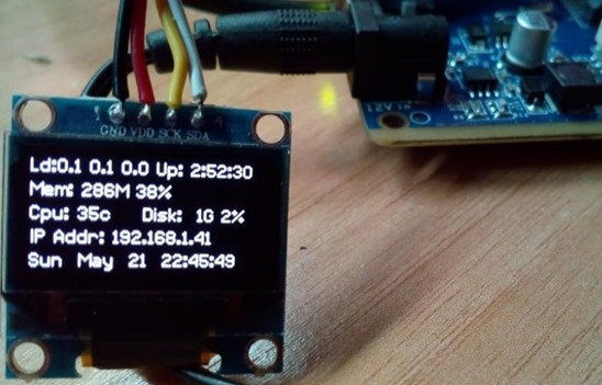
Here is my displaying some stats. As I’m planning to use a similar display with only two lines, I’ve since split the code to show 2 lines at a time, cycling continuously – but the info is the same. I managed to put a fully qualified link in the /etc/rc.conf folder – to have this run from power up.
#!/usr/bin/env python
#
# BakeBit example for the basic functions of BakeBit 128x64 OLED
#
# The BakeBit connects the NanoPi NEO and BakeBit sensors.
# You can learn more about BakeBit here: http://wiki.friendlyarm.com/BakeBit
#
# Have a question about this example? Ask on the forums here: http://www.friendlyarm.com/Forum/
#
'''
## License
The MIT License (MIT)
BakeBit: an open source platform for connecting BakeBit Sensors to the NanoPi NEO.
Copyright (C) 2016 FriendlyARM
Permission is hereby granted, free of charge, to any person obtaining a copy
of this software and associated documentation files (the "Software"), to deal
in the Software without restriction, including without limitation the rights
to use, copy, modify, merge, publish, distribute, sublicense, and/or sell
copies of the Software, and to permit persons to whom the Software is
furnished to do so, subject to the following conditions:
The above copyright notice and this permission notice shall be included in
all copies or substantial portions of the Software.
THE SOFTWARE IS PROVIDED "AS IS", WITHOUT WARRANTY OF ANY KIND, EXPRESS OR
IMPLIED, INCLUDING BUT NOT LIMITED TO THE WARRANTIES OF MERCHANTABILITY,
FITNESS FOR A PARTICULAR PURPOSE AND NONINFRINGEMENT. IN NO EVENT SHALL THE
AUTHORS OR COPYRIGHT HOLDERS BE LIABLE FOR ANY CLAIM, DAMAGES OR OTHER
LIABILITY, WHETHER IN AN ACTION OF CONTRACT, TORT OR OTHERWISE, ARISING FROM,
OUT OF OR IN CONNECTION WITH THE SOFTWARE OR THE USE OR OTHER DEALINGS IN
THE SOFTWARE.
'''
import time
import bakebit
import os
import psutil
from math import log
import multiprocessing
import platform
import socket
import bakebit_128_64_oled as oled
from PIL import Image
from PIL import ImageFont
from PIL import ImageDraw
import socket
import fcntl
import struct
import sys
from datetime import datetime
global width
width=128
global height
height=64
global image
image = Image.new('1', (width, height))
global draw
draw = ImageDraw.Draw(image)
global font10
font10 = ImageFont.truetype('/home/pi/BakeBit/Software/Python/DejaVuSansMono.ttf', 10);
def get_ip_address(ifname):
s = socket.socket(socket.AF_INET, socket.SOCK_DGRAM)
return socket.inet_ntoa(fcntl.ioctl(
s.fileno(),
0x8915, # SIOCGIFADDR
struct.pack('256s', ifname[:15])
)[20:24])
oled.init() #initialze SEEED OLED display
oled.clearDisplay() #clear the screen and set start position to top left corner
oled.setNormalDisplay() #Set display to normal mode (i.e non-inverse mode)</code> oled.setHorizontalMode() <code>#oled.setPageMode() #Set addressing mode to Page Mode
byteunits = ('B', 'KB', 'MB', 'GB', 'TB', 'PB', 'EB', 'ZB', 'YB')
def filesizeformat(value):
exponent = int(log(value, 1024))
return "%.1f %s" % (float(value) / pow(1024, exponent), byteunits[exponent])
def bytes2human(n):
"""
>>> bytes2human(10000)
'9K'
>>> bytes2human(100001221)
'95M'
"""
symbols = ('K', 'M', 'G', 'T', 'P', 'E', 'Z', 'Y')
prefix = {}
for i, s in enumerate(symbols):
prefix[s] = 1 << (i + 1) * 10
for s in reversed(symbols):
if n >= prefix[s]:
value = int(float(n) / prefix[s])
return '%s%s' % (value, s)
return "%sB" % n
def cpu_usage():
# load average, uptime
av1, av2, av3 = os.getloadavg()
tempC = ((int(open('/sys/class/thermal/thermal_zone0/temp').read()) / 1000))
return "LOAD: %.1f %.1f %.1f" \
% (av1, av2, av3)
def cpu_temperature():
# load average, uptime
av1, av2, av3 = os.getloadavg()
tempC = ((int(open('/sys/class/thermal/thermal_zone0/temp').read()) / 1000))
return "CPU TEMP: %sc" \
% (str(tempC))
def mem_usage():
usage = psutil.virtual_memory()
return "MEM FREE: %s/%s" \
% (bytes2human(usage.available), bytes2human(usage.total))
def disk_usage(dir):
usage = psutil.disk_usage(dir)
return "DISK FREE: %s/%s" \
% (bytes2human(usage.total-usage.used), bytes2human(usage.total))
def network(iface):
stat = psutil.net_io_counters(pernic=True)[iface]
return "NET: %s: Tx%s, Rx%s" % \
(iface, bytes2human(stat.bytes_sent), bytes2human(stat.bytes_recv))
def lan_ip():
f = os.popen('ifconfig eth0 | grep "inet\ addr" | cut -c 21-33')
ip = str(f.read())
# strip out trailing chars for cleaner output
return "IP: %s" % ip.rstrip('\r\n').rstrip(' ')
def stats():
global looper
draw.rectangle((0,0,width,height), outline=0, fill=0)
if looper==0:
draw.text((0, 0), 'WELCOME TO NEO2', font=font10, fill=255)
draw.text((0, 13), 'Starting up...', font=font10, fill=255)
looper=1
elif looper==1:
draw.text((0, 0), cpu_usage(), font=font10, fill=255)
draw.text((0, 13), cpu_temperature(), font=font10, fill=255)
looper=2
elif looper==2:
draw.text((0, 0), mem_usage(), font=font10, fill=255)
draw.text((0, 13), disk_usage('/'), font=font10, fill=255)
looper=3
elif looper==3:
draw.text((0, 0),"%s %s" % (platform.system(),platform.release()), font=font10, fill=255)
draw.text((0, 13), lan_ip(), font=font10, fill=255)
looper=4
else:
uptime = datetime.now() - datetime.fromtimestamp(psutil.boot_time())
draw.text((0, 0),str(datetime.now().strftime('%a %b %d %H:%M:%S')), font=font10, fill=255)
draw.text((0, 13),"UPTIME: %s" % str(uptime).split('.')[0], font=font10, fill=255)
looper=1
oled.drawImage(image)
def main():
global looper
looper = 0
while True:
stats()
if looper==0:
time.sleep(10)
else:
time.sleep(5)
if __name__ == "__main__":
try:
main()
except KeyboardInterrupt:
pass
Some GPIO
I’ve had a quick check of the schematic – I may be missing something but it appears the following GPIO remains unused… GPIO-A0, C0,C1,C2,G6,G7,G8,G9, A1 and C3 – amongst those, you have UART 1 tx and Rx – and the SPI wires… might take some subtle soldering of the NEO2 but it is do-able to get these out.
Meanwhile Antonio wanted me to test the new disk I’d fitted:
sudo apt-get install smartmontools –no-install-recommends
sudo smartctl -H /dev/sda -d sat | grep overall-health | tr -d ” ” | cut -d: -f2
The disk said “PASSED” – and so off I went to order some connectors.
Replication:
This blog entry could just keep going on forever and I could turn it into a book… I decided to have a go at making a second unit. Now, I could have started from scratch but there is a lot of work gone into this. So – I made a new SD – just a basic operating system. I put it into the second unit with a new drive and followed the steps I’ve already done right up to putting all the files onto the hard disk but I stopped before that.
It turns out you can use rsync remotely… so having mounted the hard drive and made a temporary folder – I repeated the rsync operation on the FIRST machine – but as ROOT to ensure I had permissions – but pointing as a destination the SECOND machine and that particular folder….. the destination (again addressing a ROOT connection at the other end) being root@192.168.1.44:/home/pi/tmp
And LO AND BEHOLD after asking for the password of that user, not only did it start the copy but it finished it within minutes.
I changed the settings in the boot file just as before but on the second machine this time – and rebooted. Stunningly, everything worked. I changed the domain name of course and rebooted again but I now have two identical machines both of which are now on solar.
I did have some difficulty in installing BakeBit but in the process, FriendlyArm wrote to say they had the LCD working – and they put a ROM up with the updated Ubuntu AND the Bakebit software already in there. I’m waiting for a response to confirm that this ROM will stay online and I’ll update the blog accordingly. Essentially – install the Rom, install my script (for Node-Red etc) – add in the bits to run off a hard drive and you’re done. More on that later.
Update 27/05/2017
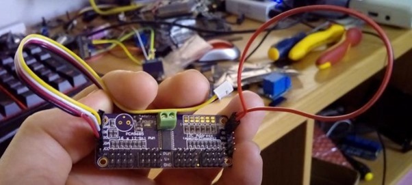
I’m waiting for confirmation from FriendlyArm but they have an image with the OLED code and example already in there. I’m hoping they’ll leave it available. It needs PSUTIL uninstalling and re-installing (2 lines) as the version they use is old – but other than that it works a treat. I DID notice that in the install is python-SMBUS and in the process of finding out what that was, I stumbled on some Adafruit code to run one of those PCA9685-based 16-channel PWM boards – you may recall some time ago I wrote about these and made my ESP8266 code compatible with them. Well, I could not resist it so I wired up one of the cheap Chinese PCA9685 boards to a connector and plugged it in.
After installing the Python library (one liner) I tried the example which outputs 2 levels of PWM for a servo. As I didn’t seem have a servo handy I tried a LED – and it worked a treat.
Then I remembered that amongst some SEEED stuff, I did indeed have a servo.
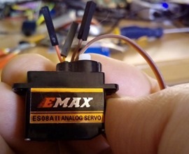 Now, if you’re not familiar with these, I guess the simplest way to explain at least this type of servo is that it is the kind of thing you see on model aircraft.
You feed it power and ground – in this case 5v… and a pulse signal – the width of the signal determines the position, accurately. I took the connector off, put on 3 new connectors and fastened it to the PWM board. Immediately it started moving from one extreme position to the other – perfectly. I can’t believe how easy this was – and that little board will handle 16 of them (not power-wise but signal-wise.
NOW I was on a roll – I rummaged around and found a TG9e servo – yellow control wire instead of white but otherwise it looked the same – would I be so lucky – yes, worked PERFECTLY. Pity they’re not a lot larger, I could put them in charge of a solar panel!
All good fun and no doubt much more to come. I was beginning to think the only way to easily access control boards like this was to get a “genuine” Pi or ESP8266/Arduino – but it seems that this view is now history. I can imagine there are lots more drivers where these came from.
The Adafruit code I mentioned above includes drivers for the BMP085 (sadly not the BME085), TCS34725 colour sensor, VCNL4000 proximity detector, MCP4725 DAC, DHT and a whole lot of other chips. Worth looking at. I’m sending off for a couple of 4-channel ADCs so I can monitor various battery voltages while the NEO2 is idling.
Port Extension
One of the things I learned early on when dealing with the NEO2 is that it does not like LOADS on it’s outputs. When I very first mastered the IO I had a bright LED on one of the outputs – and for reasons I put down to code, sometimes the board would not reset properly – or rather it would not come out of reset properly. I quickly discovered that if I removed the LED – all was well.
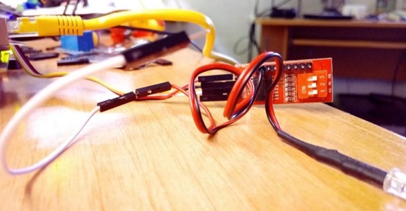
So i2c comes in as something of a relief when you consider the magically cheap PCF8754T port extenders at under £1 each.
I hooked one of these with the 3 switches all OFF to the board and did the I2cd check – port 0x20. That was a good start. The next thing – and the limit of my achievement so far was to read these. I’ve already done this with the ESP and they are REALLY easy to use – fire the address off – issue a read and BOB’s your uncle. Similarly the write.
Of course I had NO idea how to use the I2c and went looking at the BMP example in the Adafruit folder.
This is what I have – now I should say from the start… firstly I have no idea how to use the libraries and I have even less idea how to use Python. But this works – I can read the port.
So the first thing to remember is that these devices do not swap modes – they are effectively open-collector – that is to say you if you set the outputs to 1 – they can be used as inputs and shorted LOW… they float HIGH. if you use them as outputs and want to put any load on them – you need to take your load (a LED for example) from +v to the output – which will pull it LOW.
This is just as well as I could not find an 8 bit WRITE instruction – but there’s an 8 bit READ instruction with a parameter for writing to the control register… so RATHER handily you can just read, passing parameter 255. The pins will read 255 back unless you’ve shorted one or more to GROUND.
As outputs – imagine you have 8 (led+resistor) with the negative going to the pins and the common positives going to VCC, read(255) will output nothing – read (254) will turn the first LED on etc. Works a treat. The only thing I don’t like about the cheap extender boards – come on guys – some more ground and VCC connections would have been nice!!!
From sheer guesswork to this…
#!/usr/bin/python
from Adafruit_I2C import Adafruit_I2Ci2c = Adafruit_I2C(0x20)
port = i2c.readU8(254)
print port
It doesn’t get any easier than this – clearly here you are importing the Adafruit library. I had to put the library in the same folder as my code as I have no idea how to make a shortcut to it – which is apparently how it is done elsewhere.
i2c is what I would call an object (could be any name)– no idea what you call it in Python… and so you call the I2c setup function with an address – i.e. the address of the board and you get your object(i2c) back. i2c.readU8 is a function you pass a value to – and it returns an 8-bit number. Simple as that. Make the number you pass 255 for all inputs, anything you want as a LOW output you simply invert that bit….. 254, 253 etc.
I’m sure someone will tell me there is a write function and that’s fine as I’m still new to this (I’m a whizz at C). And, erm, well, it works – so there’s your port extender – you could have 8 of them with different addresses – that’s 64 bits and if you mess something up in hardware, there’s a chance your NEO2 will survive!! I will modify this as I get more clued up!
Update 25/July/2017 – Having just discovered a better way to run SD1306 displays from Python (see relevant post – https://tech.scargill.net/ssd1306-on-the-neo-plus2/) I did this again – this time the /mnt directory was being awkward when setting up the hard drive so I just made a directory called /stuff. I had also missed out the need to change directory into /boot before processing the boot file – that is now fixed.

Log2Ram will not mess with apache anymore since the 11 april : https://github.com/azlux/log2ram/commit/05a31e0e358ca00f2686191b3958b0a777cfb081
The write on reboot work now. Open an issue if you still have problem.
Good evening.
That’s excellent news – other than the entire installation was later than 11th of April? Matters not now I know what to look for. It occurs to me that when this happens – all you have to do is create a log folder for Apache… and my thinking is.. so why doesn’t Apache just do this if the folder is missing? Just a thought.
Pete.
We have a NanoHat Motor module, it use PCA9685 too. And with 12V Power supply, to drive various motors, such as PWM steering motors, four-wire step motors, or DC motors.
http://wiki.friendlyarm.com/wiki/index.php/NanoHat_Motor
Excellent – well now I know how to read and write bytes to I2c, just about anything should be possible… A/D convertor next so I can monitor my various power outputs (5v, 12v, 24v and the solar output)… all good fun.
Hi Pete,
Please write a post about your solar system, the echipament you use, the amount of energy you harvest daily, why do you choose a solar system instead of a less expensive power bank ……. all the experience you have on this domain.
You and Andreas Spiess are my favorite engineers 🙂
Keep up the good work
Hi there Ion
Well, it doesn’t need a blog item for that. Right now I’ve just given two small 40w panels to my neighbour so he can have a tinker.. and I’ve fitted a 250w unit. I have two 100AH 12 batteries running in 24v mode with a decent solar regulator running the lot. That is outside and powers all the 12v outside lighting including the Pergola via a buck convertor. The batteries charge by lunchtime at the latest here in Spain so I’ve also brought a cable from the panel to 4 7AH batteries – again running 24v again with a decent regulator. Another buck brings out 12v and 5v and that runs internal lighting in my office and the two NanoPi units – it will run a lot more but I’ve only just finished fitting it up. Why solar – I in turn was given the large solar panel so that side of it cost me nothing. I’m getting a feel for it and once the ridiculous laws in Spain change (when they get a government I guess) I’ll expand the solar side. Of course we have mains electricity and have just taken advantage of a 2-hours-per-day free electricity offer to do the heavy stuff.
Enjoy.
Hmmm …. free electricity from sun ….. sound nice, but is this really free ?
The solar panel costs around 1.5$/w + solar regulator (10$ a very cheap device) + power bank (the price of the batteries is high and the life is short – around 2 years for a daily discharge).
In 7 hours of full sun you get 40W * 7h/day = 280W
280W * 25 sunny days in a month (even in Spain is raining and there are clouds in the sky) * 12 months = 84KW
8KW costs in Romania 1$ from the energy supplier, so 84kW costs around 11$. In 6 years I just get the money back for the solar panel
Finally solar panels are nice toys, but the energy is not free at all.
Not sure you read my reply Ion – the solar panel was free – i.e. it didn’t cost me anything. I don’t care if it costs money – I’m learning. I wonder if you’ve been to Spain – the place is littered with them – HUGE installations including one of the biggest solar collectors in the world. Of interest, 8KW here in Spain costs a lot more than 1$. Our bill for last month along was nearly $300
As for the cost of panels – there are a lot of second hand panels coming on the market. A company in the UK is currently selling 250w panels at around £80 – I have a pal who is about to install I think 66 of them here in Spain. That’s a solar panel cost of around 30 pence per Kw. Mind you he’s off grid and wants to charge his Tesla….
And as for solar being a toy, in the UK last Friday, solar generated 24% of all electricity produced. On 10th of May it was not far behind. Not the norm but an example of what can happen. If that is toy, what is coal power at 1.4% – keep an eye out for even greater achievements – I just read about this… https://www.digitaltrends.com/cool-tech/china-floating-solar-power-plant/?utm_source=feedly&utm_medium=webfeeds
while this is total bullshit: https://www.youtube.com/watch?v=GtkbioiQHmA
I can see I should really have made this a subject in it’s own right – yes, solar roadways – what a laugh – in the UK they’d be covered in mud within a day. Funny enough – someone who I know who does solar installations cannot stress highly enough the importance of keeping the panels clean.
in other videos by Dave Jones you see them crashed, blistered, full of moist, and so on… the road ones, of course…