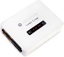
 I recently took a look at the ZeroPlus Arduino Starter Kit – well, this logic analyser is not a starter version! This particular model, the Lap-C 322000 has 32 channels and a bandwidth of 75Mhz. It has 64Mb memory, 2Mbit per-channel depth and is the top of the line in the LAP-C range. The unit comes complete with manual, probes and hard case and works on USB 1.1 and USB 2.0 – Read on…
There is also a 16-channel version of this unit and clearly the price will vary depending on the facilities. The manual makes no reference to Windows 10 but does state compatibility for everything from Windows 2000 to Windows 7 (32 bit and 64 bit).
The manual I THINK assumes a CD is provided as it recommends you find the START.EXE program without saying where that comes from. Thankfully the ZeroPlus website downloads section took care of that. My package did not come with a CD.
Up to version 13.13.05 there was separate software for various versions – but today I grabbed v3.14.03 dated 21st November 2017 (90MB file) which is common to all.
While I’m waiting for the download – the zipped case is clearly intended to take a hammering – padded internally and hard outside. There are pouches for leads and probe heads. 32 heads were supplied, 4 each of 8 colours.
These analysers differ from the cheap Saleae units in that they have lots of internal sample memory. There is also sample compression and hence (apparently) that gives up effectively up to 8 times the capacity you’d get without compression.
 As I noticed with the Arduino Starter Kit, the downloads from their website are slow – this might of course be partly due to me being in the UK and the site being in Taiwan.
Inside the ZIP file which refers to all models, there is in fact a single setup file. I’m running Windows 10, 64 bit and I set about running the SETUP.EXE file.
The driver section ran without any issues and so I ran the application setup. After a brief delay, I noted the icon appear on my desktop. The software found the analyser and started up without issue.
You would expect this to work flawlessly as these systems are not cheap and clearly there is a lot of counterfeit hardware out there at much lower cost – they have to have an edge and the claim is that the edge is in the software. It installed perfectly and operated without a hitch.
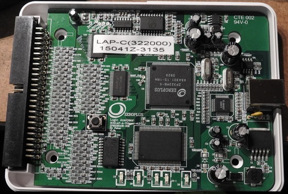
I figured you might want to see what’s inside that little white box. Basically one button and this (you should be able to zoom into this image)..
The software itself looks great, though I did end up wasting a little time studying the MSO section – but it turns out that this is for a completely separate module which is not part of the basic Logic Cube. Would have been nice if they’d disabled this!!!
The unit handles up to 75Mhz unlike the cheap Saleae units which handle CONSIDERABLY lower speeds – so this would be handy for example for SPI which can use comparable clock speeds.
The software of course, on a product like this – is going to be comprehensive.
Apparently if you’re not on Windows this hardware is apparently supported by Sigrok.
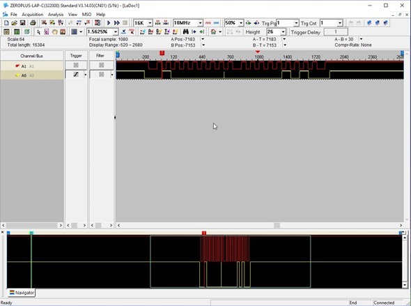
For simple testing, having 32 channels to play with is a bit daunting, and I quickly found out that you could turn off all or some channels. As I already had a board on the bench with some I2c information available, I reduced the number of channels to two – and took a sample.
As with the beginners kit reviewed separately, the I2c data line came up in dark brown which is barely visible– however this time – a simple right click allowed me to select my own colour.
Sure enough, that looked like the data I was expecting – but how to analyse… in the beginners kit it was easy… where the latter has just over 30 protocols, this software comes with over 120 protocols!! That intimidation didn’t last long as the controls, one by one became obvious.
I set the samples to 16k (range on this unit 2K-4M) and the speed to 10M (way overkill) – range available 100Hz to 200Mhz. I had a bit of an experiment as you’ll see in the video below and found that using the Arduino to supply I2c I could actually sample as low as 200Khz but of course I2c can in fact go WAY beyond that so 10M seems a more than reasonable sampling rate.
It turns out that before you can analyse the signals – you have to group them into a bus – easily done – select the signals you want – group into a bus – select protocol and sure enough – pretty much instantly… a result…
Something I found a little annoying – as someone who’s eyesight is very good but has been better, despite only showing 2 channels now, I could not seem to find how to stretch them to fill the screen. I understand this is something that is on their top of the range models but surely that’s an easy enough thing to do for all models?
The software has buttons on the top to allow multi-screen users to select either monitor or stretch the display over 2 monitors.
Here is a quick demo of the software and hardware in action on a simple I2c signal.


also compatible with win 10 !
I am using windows 10 64 bit.
Amazon has it for $1599, while the 16-bit model is $135. Weird.
…ho il modello 32016 il più piccolo ma è fantasticico…
it’s an english blog…
No, It’s a British blog…