
With so many smart switches and sockets out there, how do you differentiate your product? It looks like Blitzwolf have done just that. Small enough to fit inside a back-box and comes complete with a detachable clip–on bracket – the at first glance has a future in my home.
This Blitzwolf power switching device handles 10A (2300w MAX non-inductive) at 110-240v and runs on 2.4Ghz WiFi. On the bottom are 6 connections with corresponding screws on the front panel. Live, Neutral in, two relay-switched-live outputs and two button inputs. There are no internal test buttons as this unit is intended for out of sight use but you could use one or two switches – beware however that the connections are wired to the mains – don’t ever touch the connections while this unit is live.
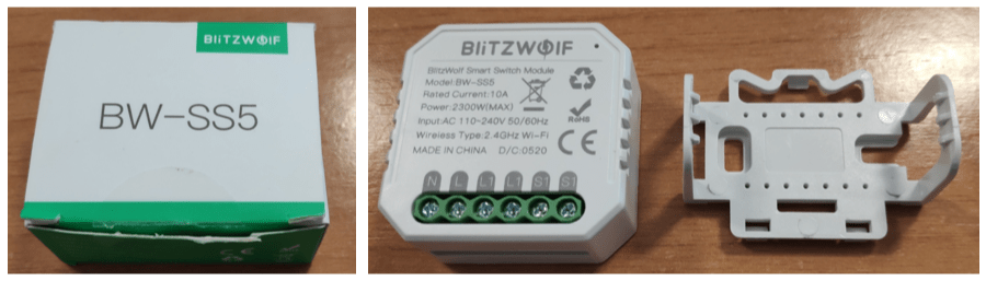
The (multi-language – English, French, German, Italian and Chinese) manual of course states that installation should be carried out by a qualified electrician – so I guess that excludes those of us who’ve been working in electronics for half a century or more, wired up hundreds of smart home devices but never became electricians 🙂
The BW-SS5 does of course work with the “Blitzwolf” app out of the box if you want to go down that route (pairing takes seconds), but also works with Tasmota – and here is the template from the Blakadder site. But read on…

And here is the wiring straight from the little booklet that comes with the BW-SS5.

But I have a couple of gripes about this neat little device is: I hate this practice of using the same name for two different products – remember the Blitzwolf BP-SHP10 I wrote about ages ago (the link takes you to that article)…. that device was supposed to have power monitoring – it turned out there were two different versions – one HAD power monitoring, the other did not. The ONLY difference between the two was/is the barcode on the box (who keeps boxes).
Well, they’ve almost done it again, there are TWO BW-SS5 units and again the only differences are the bar code area on the box and (according to subscriber Marko), a variation in the labelling on the crew teminals. Otherwise, my BW-SS5 SINGLE-GANG unit looks just like the DUAL gang version. The give-away came when I plugged the unit into 220v, switched it off and on 5 times as per the instructions and “paired” it with the Blitzwolf APP (during which time a little light appears – one you never see after that – I’d rather have it show when the relay is on).
Before anyone says – “this unit is intended for use in a box – why would it need a LED?” – after 9 months away from Spain, partly thanks to Covid, earlier this week I had my wife giving me ear-ache as to why our hot-tub wasn’t working. I had no idea so I went into the fuse-box in desperation only to find inside a Sonoff BASIC which I’d set last year (and forgotten about) to work only during off-peak hours. A quick push of the Sonoff button and the red light told me that all was well.
Instead of TWO on-screen buttons on the APP once I’d set it up for the BW-SS5, there was ONE. And THEN I took a close look at the box. The bar code label says “1-gang”. So, see that image above, about the BW-SS5 2-gang switch and Tasmota – I’m wondering if that is compatible with my single-gang BW-SS5.
My trusty TUYA-CONVERT combo of Orange-Pi ZERO and ESP8266 is set up for my UK network – which has a different subnet to the one here in Spain so with help from Antonio I just added the UK network into the setup here.
Tuya-convert would NOT work for me on this board and initially, several attempts at flashing using the soldering iron failed. The unit did, however, still pair with the Blitzwolf APP without issue.
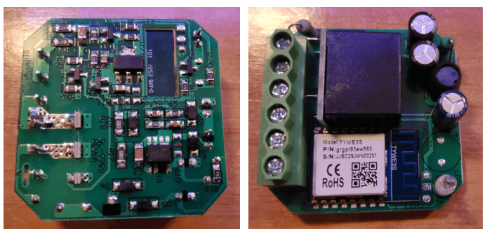
Initially I tried and failed to solder the 3v3 pad as it is right next to the relay. I eventually got power and ground from underneath (the regulator – big pads) none of which helped with my programming efforts at first – that is until simultaneously I was trying out my new Daniu PX-998 (name says Hanstar PX-998 on the box) soldering iron and some cheap non-lead-free solder – and reading the comment (plus photo) in here by blog subscriber “marko”.
Armed with this new information, I had another attempt at soldering 3v3, gnd, rx, tx and gpio0 as suggested by Marko – then using the latest Tasmotizer-1.1c.exe (in Windows) I successfully flashed Tasmota onto the BW-SS5 – NO PROBLEM. I honestly have no idea where the turning point occurred but it all just worked (Mr Shark – Antonio) had already suggested I needed the latest Tasmota) and now I have a more or less perfect, Tasmotized single-channel BW-SS5.
By “more or less” I mean that right now the two switch contacts (S1 and S1) do nothing but that’s probably a minor issue in the template – I’ll delete this para when it is fixed.
Mar 6, 2021: I just upgraded to Tasmota 9.3.1.1 development version by OTA, ensured my settings were as here and shorting the S1 and S1 contacts still does nothing – does anyone know any better?

End of update.
Oh, one last tiny thing – the BW-SS5. Sitting in my darkened office here in sunny Spain, my desk is around 29c. After I plugged the BW-SS5 into the 220v mains supply – with no load connected, I left it to sit for 10 minutes while updating this blog – its temperature at the end of that was 36c.
I got the same issue. the solution to it was to set the SwitchDebounce back to default 50.
Apparently there are versions of BW-SS5 that do not require to activate the AC frequency detection feature.
Hi Peter,
What i described, clearing the config, setting the template parameter in blakadder worked for me.
Hope it does for you too.
BRGDS
Schematic:
Yup, lovely…. thanks.
Hi Peter,
I have a few 2 gang and a few 1 gang and im running into the same issues as you.
BRGDS
Oh dear, one day this week when I’m low on jobs I’m going to investigate further. Found a “proper” switch to wire in…. cheap though…
My plan for today after work:
1) downgrade one to 9.10 (I think I loaded them with 9.3.1)
2) Wipe the config
3) Use the template in https://templates.blakadder.com/blitzwolf_BW-SS5.html
4) Set to SwitchMode 7 when using a standard wall switch to toggle relay state.
I will post the results of that test here.
BRGDS
That would be appreciated, thanks. Mine was on 9.1 and I upgraded it to the dev version 9.3.1.1 – no difference.
I just tried to convert a 2-channel bw-ss5 with tuya-convert without success. I never used tuya-convert before but it seems to work. I think i will have to solder (as i did many times before on other devices) or did anyone have success with tuya-convert on the 2-gang bw-ss5?
My impression is that Tuya-convert is now dead. Am I wrong?
As Keith Morgan mentioned some posts before – it was extremely easy to solder my serial to usb converter. Tasmotizer …
Anyone? I never did get the two S1 contacts to do anything on my single gang SS5 – so today I upgraded to Tasmota 9.3.1.1 dev and using the template here… https://templates.blakadder.com/blitzwolf_BW-SS5.html
I set up the ports as per the right side of that page – i.e. GPIO12 is thw switch – the relay and green LED work just fine but the two S1 pins when shorted still do nothing. Any ideas?
Im not sure if i understand what you say. You were able to flash tasmota but not able to use the L1 as switch for the L1? Did you use mains power on S1?
Hi Nate
Tasmota flashed no problem – and OTA’d to latest version no problem – Blakadder template – in both cases the BW-SS5 is mains powered – the relay and light work no problem…and turn on and off from the WebUI – but shorting the two S1 contacts together then opening them does nothing.
I dont have a 1-gang. But for the 2-gang the lightswitch should short L (mains) with s1 or s2. I think the 1-gang has 2 Terminals for the 1 channel so shorting between the two s1 terminals wont work. You can check this with a multimeter (disconnect from mains first) on continuity testing between s1 and s1. I guess it is always connected.
There are times when I wonder how I get out of bed in the morning – you are of course right… the two S1s are identical – switching occurs between S1 and live. I can get it to work – kind of – I just tried both switchmode 0 and switchmode 1 and it isn’t quite right – but at least it is doing something. I need a proper switch to test with rather than multimeter leads 🙂
🙂 i can feel you haha…
I saw this. Maybe it helps on switching:
SwitchDebounce 69 https://templates.blakadder.com/blitzwolf_BW-SS5_2.html
Keep going… I just did that switchdebounce – and now with my bit of dangously thin wire across live and the second S1, once, it swiched off the light…. most of the time it seems to switch the relay then the relay ends up back where it was – so clearly we need a setting for people who cant be bothered to fit a proper switch 🙂
Hi there! Thanks for your thoughts on the device.
I’m still new in this world out home automation an I’m doing my homework looking into the different options of device and use cases.
Regarding this specific device I have a question: Did you have problems with this device heating up when load is connected? Another question that I have is what is the life expectancy of this devices?
Best regards
I had no problem but then again I didn’t push the load to the limit. As for life expectancy – that will be down to build quality, load and other factors – have you thought of contacting Blitzwolf with that question. Ultimately only you can really judge how long such a device will last in your application.
That’s a screen grab from the Banggood mobile site at https://uk-m.banggood.com/BlitzWolf-BW-SS5-1-Gang-or-2-Gang-Two-Way-10A-2300W-WIFI-Smart-Switch-Module-APP-Remote-Controller-Group-Control-Timer-p-1645429.html
A user named ‘taste’ has kindly provided 3 labelled photos including the serial programming pins inside a 2-gang BW-SS5, although you can programme OTA with tuya-convert to avoid opening the case.
Oooooh…..
Thanks Keith,
I can confirm that this pin-out works and I was able to tasmotize one using a serial connection.
I didn’t know the OTA option with the tuya-convert, and yes, as you say, it works like a charm.
Thank you for your help!
i have found this at banggood . I don’t proof it. but may be it could help to flash tasmota on it.
Sorry I’m not following this…
Hi! I’ve just programmed one following this pin-out. Superb!
In my tests I tried this pin as GPIO0, however I was disconnecting it from gnd after boot, I was wrong thinking that it only needs to be grounded at boot time. Grrrr.
Anyway, now it’s working. Next step, find a template for it 😉
Thanks a lot for the pic. 🙂
2 gang can be flashed with tuya OTA.
1 gang only with serial (strange but true)
Agree on 1-gang (no experience of 2-gang version yet). It will program with serial only – but why? There can’t be that much difference between the 1 and 2 gang versions – surely…
The two versions are very different internally, with the 2-gang version having a piezo-electric buzzer and no LED but it does have an on-board reset switch.
When the 2-gang version is first powered up the buzzer ‘beeps’ intermittently instead of a LED, and the unit can be flashed OTA with tuya-convert during this time. I have successfully put the latest Tasmota 8.5.1 onto three x 2-gang units today.
You can see from my photo that the 1-gang unit has a LED under the small hole in the case, whereas the 2-gang unit has a press button. The user manual is a bit confusing as it seems to be the same manual for both 1 & 2 gang units, despite there being no LED on the 2 gang and no switch on the 1-gang. The manual says to press the ‘traditional switch’ 5 times at short interval to put it into pairing mode or press the reset for about 10 seconds. When I interrupt the power to the 1-gang unit 5 times the LED does flash in the pairing pattern, but I haven’t yet managed to use tuya-convert successfully on it.
Thanks for your 2 responses above, Keith… when I’m done catching up with today’s email mountain I’ll come back to this. Magic. Ok, you have to satisfy my curiosity … why 2 different IP adddesses.. the screen grab comment starts with 79… the 2-gang comment starts with 80.. mobile and PC?
Thanks Peter, I wouldn’t have got this far without your excellent Tech Blog which is what got me started on the whole Tasmota thing. I used your Script to get me going with MQTT on two Raspberry Pis. I too have ‘A Place in the Sun’ and now have an extensive installation of Sonoff, 2NICE and BlitzWolf BW-SHP10 units controlling security cameras and lights in my two locations. Re my IP addresses, as although I use OpenvVPN plus 2 dynamic IP addresses, I commented on my PC and my mobile is usually WiFi via the 79 address so I may have had an ISP IP change between the 2 postings. Strange.
Keith – youve opened up a can of worms here. What on earth is a 2NICE aand why don’t I have any? I read your response and went off to find their website – I could only find an Amazon entry… So off I went to find the shenzhen TanTan company – got that – no contact though and no lights – only USA plugs, well I tried…. my pal Aidan just Discord’d me yesterday – he has several fixed IPs, I’m intensely jealous – I have to pay 6 Euros a month for my one and only fixed Spanish IP (the one in the UK came as standard with Voda fibre. It’s long overdue time that IPV6 became the norm so we could all have hundreds of fixed IPs… millions, thinking about it 🙂 – ok, I’m done.
Peter, feel free to email me directly if you want a bit of detail on the path I took. I try do it all on the cheap – don’t like pay for fixed IP addresses – so I use various (for resilience) ddclient services running on Raspberry Pis to update a free* DNS service whenever my ISPs change my dynamic IP addresses. *such as afraid.org but there are other Free DNS services out there.
As for my (UK) 2NICE UP111 Power Monitoring Plugs, see https://templates.blakadder.com/2nice-UP111.html and https://www.amazon.co.uk/dp/B07ZQ34X55 currently priced as a 4 pack for £31.99. They can be flashed OTA with Tasmota via tuya-convert and have built-in power monitoring, and I bought them on the strength of the reviews after getting my fingers burnt by accidentally buying similar looking but unsupportable LSPA7 devices on ebay – only then did I read https://templates.blakadder.com/unsupported/anoopsyche_LSPA7.html
So you can use Tuya-Convert to flash it?
Didn’t work for me on the 1-gang and I’ve not yet tested the 2-gang.
Hi!
Does anyone tried to flash a 2-gang version of the Blitzwolf BW-SS5?
After reading this article and receiving one 2-gang switch I’m not being able to tasmotize it.
After opening and inspecting the device I’ve desoldered a kinda little riser board where a unknown to me ESP8266 chip variant is placed. I’ve done that because underside some labels on the pcb seemed to indicate for what the pins were for.
Unlucky me, I’m not able to locate the GPIO0 as the chip is unlabeled and I’ve never seen one like this, it has engraved on the RF shield the label: 2020.3.26/pdka -maybe other letters as the font is extremely small-. I suppose that this label is the fabrication date or something similar. Its an strange ESP8266 to me, it has only 6 pins in three of it sides.
The other pins, +3.3v, GND, Rx and Tx are labeled on the PCB so I suppose that they’re correct. Maybe I’m supposing too much.
I’ve tried to use the push button thinking that maybe it was tied to GPIO0 but it didn’t work. Also, in the bottom layer of the PCB, there is a reset label (purple in the image) which also made esptool.py read_mac fail.
Also I’ve tried to find similarities with other ESP8266 versions but I’m not able to find one with six pins on each of its three sides.
I’m attaching to this post some pics I’ve taken, so maybe any of you can recognize the chip so I’m able to do the proper connections.
Thanks in advance 😉
Ooops, the image wasn’t uploaded.
Here you are 😉
Oh, very different to the 1-gang version, which has no button
GPIO0 is the first pin on bottom left labelled IOO.
I have successfully flashed ESPHome over serial without desoldering ESP board by connecting pin IOO to GND and connecting USB->TTL to pins GND, RX, TX and +3.3V (last pin next to RST pin) on first try.
Just flashed 1 gang with Tasmotizer(serial).
Template is {“NAME”:”BlitzWolf SS5 1 Gang”,”GPIO”:[0,0,0,0,0,0,0,0,9,21,0,0,0],”FLAG”:0,”BASE”:18}
For use existing wall switch set “switchmode 7”.
How did I miss this ??? Soldering iron at the ready – BW-SS5 at the ready… latest Tasmota yet to download…
Alll seems to work except shorting the two switch contacts does nothing. Relay works – can toggle on and off in tasmota – but nothing from S1-S1 when shorted…
Tasmota >= 8.4,
SwitchDebounce 69
I just realised what I was doing wrong – S1 to S1 – incorrect – they are identical – the correct switch wiring is the outer S1 to live. St the same time I made that SwitchDebounce 69 change – I’m getting a quick toggle of the relay (then back) when I short live and the outer S1 – that’s not right…
Please check if button pins S1 and S2 are protected or not.
Can I use them as output ? or for one wire sensors DS18b20 ?
Did you find the schematic for BW-SS5 ?
3v3 should be available on the other side of the board, there’s a voltage regulator. Fire up the multimeter to find the exact pin!
Module has different label on the screw terminals for each model.
Thanks for the correction, Marko – blog duly updated. This morning, once I find a new bit for my soldering iron I’ll get on trying to reprogram this board.