So much going on today I thought I’d put the lot into one blog entry.
So, I’ve spent the day with my pal playing with one of several IOT solutions – familiar to regular readers – node-red-contrib-ui. This just keeps getting better.
 So we spent our afternoon getting to grips with the new “template” node which Andrei the designer has been improving recently. We wanted an RGB controller which the UI does not (did not) currently feature. Getting to grips with Angular and how it interfaces with the UI is proving a challenge but the long and short of it is (I know a couple of you are about to get excited) – we have a working RGB controller.
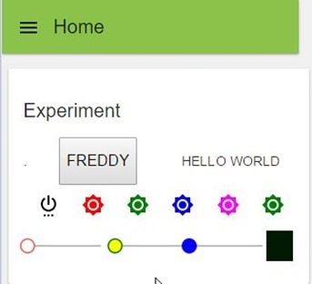
Here it is. Just ignore my FREDDY experiments and the pretty coloured line of buttons…
Well, no, don’t ignore the buttons – I’m finding increasingly frustrating to have to use the big but still limited range of ANGULAR icons – so I’m about to write off to Andrei to see if we can maybe trap HTTP in the icon description to allow us to use any arbitrary online PNG file – preferably transparent ones – imagine you have a row of buttons for +, minus and auto. The Angular icons do + and – but how on earth do you represent “AUTO” – I could think of a 1000 examples where you just can’t do it with a limited set of icons… so that needs work…
Update 31/12/2015 – It is now my understanding that soon we will have the ability to use our own images as well as an expanded library – that is just excellent!!!
However I digress – see the bottom line – RED GREEN AND BLUE controllers (ignore the yellow, I’m experimenting). On the right is a BLACK BLOCK which changes colour as you move the sliders. So this TEMPLATE node in Node-Red UI- and this is all down to Andrei, has an input and an output – the output puts out JSON string with R G B values…. the input expects msg.payload.r, msg.payload.g etc… well I didn’t have a CLUE how to do that so again Andrei helped. So here I will show you an example of use –, the template node and the input to manually set the controls. I CAN CONFIRM that all of this mirrors perfectly if for example you have this running on 2 phones at once – they remain in sync perfectly!!!! This is just so good!
So above you see an inject (ignore the timestamp) – the function will set up 3 values to put into the template to affect the sliders – so for example you can set up initial conditions.
msg.payload = {
r: 10,
g: 50,
b: 100
};msg.payload.b=190;
return msg;
So there’s an incoming payload which we’re going to ignore – the bit I was not sure about was adding new stuff – ie msg.payload.r and again Andrei came to the rescue – you’ll see I’ve initialised RGB values and then proven to myself that you can quickly alter them before sending MSG off to the template node. The output of the template node goes off in this case to a DEBUG node and there’s a JSON string with RGB values going out (that might be used to populate a global variable and off via MQTT to some RGB lighting).
Here is the content of the template.
<div layout=”row” layout-align=”space-between center”>
<md-slider ng-model=”msg.payload.r” ng-change=”send(msg)” flex=”30″ min=”0″ max=”255″ class=”slider-red”>
</md-slider>
<md-slider ng-model=”msg.payload.g” ng-change=”send(msg)” flex=”30″ min=”0″ max=”255″ class=”slider-green”>
</md-slider>
<md-slider ng-model=”msg.payload.b” ng-change=”send(msg)” flex=”30″ min=”0″ max=”255″ class=”slider-blue”>
</md-slider>
<div style=”width: 32px; height: 32px;” ng-style=”{‘background-color’: (‘rgb(%d, %d, %d)’|sprintf:msg.payload.r:msg.payload.g:msg.payload.b)}”>
</div>
</div><script>
(function(scope) {
scope.$watch(‘msg.payload’, function (v) {
if (!v) scope.msg ={ payload: {r:0, g:0, b:0} };
});
})(scope);
</script><style>
.slider-green .md-track-fill {
background-color: green !important;
}
.slider-green .md-thumb:after {
background-color: green !important;
border-color: green !important;
}
.slider-blue .md-track-fill {
background-color: blue !important;
}
.slider-blue .md-thumb:after {
background-color: blue !important;
border-color: blue !important;
}
</style>
What you have there is not only the RGB controls – but all you need to know in order to make any custom system you like which has INPUTS and OUTPUTS. This is so very useful.
So there you go – a great new UI gadget.
Strangely enough – I needed that bit of knowledge about adding stuff to MSG as today another pal of mine pointed me to an ANDROID/IOS App called OWNTRACKS. It has a lot of uses but one of it’s features allows you to set up your phone to send regular LONGITUDE/LATITUDE messages to your own MQTT server.
Now, I went off on a crawl and found a NODE-RED node to do GEOFENCING – here it is.
So the ORANGE node is a node called GEOFENCE (node-red-contrib-geofence). This is marvellous – so you feed it longitude and latitude and it compares against a set area and either passes the message through – or not.
On the left you see my MQTT node picking up a topic which I set on the phone. Next you see me convert the data to the right vars – exactly the same issue I had above so I killed 2 birds with one stone – here’s the function.
var fred=JSON.parse(msg.payload);
msg.location = {
lon: 0,
lat: 50
};msg.location.lon=fred.lon;
msg.location.lat=fred.lat;
return msg;
So from my incoming MQTT in a format decided by the App, not me I’ve created 2 items which the geofence node understands – regular updates as to where I am.
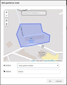
Here’s the winner – the Geofence admin page when you click on the orange Geofence node.
This is so good I’m betting I don’t have to explain how it works – you simply put a square, circle or shape around a location, town, house or whatever – and if the incoming coordinates are in that area the whole message just gets passed through – if not, nothing gets passed through. There are other options!!
The obvious next move is a function with a check to ensure you were OUT of the area and coming IN and the string “I’m nearly home, get the kettle on” – passed to the speech system I showed you in my last blog. In my case I’d likely get beaten up for doing that but I’m sure you understand the MASSIVE potential for this.
Put welcome lights on when coming home, alarm the house when leaving etc etc etc… actually with an ESP8266 you could put the kettle on yourself!!! HEY that’s a good idea.
All of this takes only minutes to get going when you have info like this (I had to kind of fumble through much of it). You could use multiple nodes from the same MQTT input to do all sorts of analysis on movement. What’s needed next it really  cheap GPS transmitters for the cats!! Just so many possibilities.
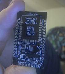
So – that was that – then when I got home tonight – the post was waiting for me. This little number arrived in the post.. This bare board was less than £2 on Ebay… http://www.ebay.co.uk/itm/172017546015?_trksid=p2057872.m2749.l2649&var=470889509954&ssPageName=STRK%3AMEBIDX%3AIT
Ok, it needs 2 MOSFETS, a couple of resistors (SMT) and a regulator and an ESP-12 and you have yourself a handy 0.1” centres development board – only for true soldering iron enthusiasts but I thought it would be worth having.
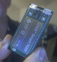
 As well as that, SEED STUDIOS sent me their LinkIT SMART 7699 board and a nice adaptor to go with it… I’ll have to write this up later when I get enough time to do it justice but on the left you see one of the little boards – it has 2 micro-USB sockets – 3 buttons (reset, program, user) and a WIFI module with lots of IO – the accompanying breakout board lets you do the whole thing with wires and connectors without going anywhere near a soldering iron.
Unlike ESPs (which are of course cheaper) these little devils run Linux!! Anyway, it’s late but here’s a link for interested parties.. http://labs.mediatek.com/site/global/developer_tools/mediatek_linkit_smart_7688/whatis_7688/index.gsp
And that is about it for one day. I’ve just found a cheap TIMER unit for my upstairs radiators so I can turn them off when we’re sleeping downstairs and by the time that turns up I’ll have a very pretty mobile application for my good lady to control the heating with.
Good night, all.


Peter, I replied to a post you made in the Node-RED UI Google Group and figured I’d post it here to help some people that may have had the same issue with md-slider sending being jerky and sending many intermediate messages are you’re sliding it around. The solutions is to make it send a message only after you finish moving the slider.
I had the same issue and found the solution in the Angular Material slider docs. All you have to do, is add an md-discrete attribute to your , as in:
And you’re done! This does 2 things. One, the selected slider value is only sent when you release the slider! And two, as you touch the contorl dot it transforms to a teardrop showing the value above (for horizontal sliders) and beside (for vertical sliders) which I find very useful!
Give it a try. Here’s a demo from the Angular Material docs. Look at the last demo, last slider bottom right labeled Master:
https://material.angularjs.org/latest/demo/slider
Well done – I’ll give that a try….
oops it seems the HTML code I posted didn’t show correctly. Trying again
<md-slider md-discrete ng-model=”msg.payload.g” ng-change=”send(msg)” flex=”30″ min=”0″ max=”255″ class=”slider-green”>
</md-slider>
Cancellor – I believe James is talking about DIY using 433Mhz off the shelf UK mains switches as you’d find at many DIY stores, controlled by DIY simple cheap 433Mhz transmitters such as these http://www.ebay.co.uk/itm/181887578833
If you’re prepared to do a bit of WIFI sniffing this is a great way to get cheap control – and those cheap transmitters incidentally work a treat at 12v giving way more power output and they are easy to control with, say, Arduino – BUT – it’s a one-way process like the old X-10 – you don’t ACTUALLY know if it has done anything and many things can affect signal reliability. I prefer WIFI with confirmation most of the time.
A better way is to use something like an ESP-01 or similar with power supply and relay with true MQTT software such as that I use in our home control project (Home Control 2015 on the blog here) – the problem THERE is cost and boxing etc.
But help is at hand – shortly into the New Year I’ll be testing and blogging a new and inexpensive light controller and mains control box, ready made at prices not far off. Keep an eye on the blog, it is all down to how long shipping takes. I’m quite excited.
I went down the 43Mhz route years ago along with the NRF24L01 2.4Ghz modules – if you look back far enough in the blog you’ll see it is all detailed.
I’ve been using these remote control sockets for a couple of months now and found them to be very reliable.
I’m using an el cheapo 433MHz transmitter module and running it at 5V. It”s controlling 7 remote sockets. Some are in the same room (but it’s a big room – about 10m long) and some are upstairs at the other end of the house. The house is not small and all the internal walls are brick.
Initially I was using a Pi to drive the transmitter. I used PiLight to sniff the remote codes and then programmed the Pi to transmit them.
I then switched over to using a NodeMCU board running an Arduino sketch to do the transmitting. That is MUCH easier because you can simply use the rcswitch library and use commands like rcswitchon(a,b) where a is the channel number from 1 to 4 and b is the device number from 1 to 4. So you don’t need to do any sniffing of remote codes.
The sockets I use are Maplin ones but I’ve seen plenty of identical looking unbranded ones at lower prices on eBay.
Pete – is the unit you’re going to be testing that one you sent me a link to the other day?
Looking forward to hearing about your mains control box. You are right that 433MHz isn’t ideal – I went down the same NRF24L01 route before the ESP8266 came out but that was for bidirectional stuff and it was a massive pain in comparison to wifi and MQTT.
The sockets though I have found to be very reliable and having made a MQTT bridge to them using an ESP8266 and the module you mentioned I am very happy with the results.
Taking about putting the kettle on you might be interested in the fact that I have some UK plugs controllable over mqtt and they’re cheap too at about £5 each. Not sure if that is useful in your continued quest for ever more automation.
Tell me more! Where did you get them from?
Pete – on the subject of UI for home automation, I am starting to have a play with openremote.org.
There are a number of youtube videos on it. The nice thing about it is that it has a wonderful looking RGB control and multiple screens with navigation. You create the screens online and your own server shares the designs with ios and android devices.
I have also seen that Andrew Lindsay had it working some time ago: http://blog.thiseldo.co.uk/?p=964
It seems complicated (at first glance) to set up though.
Tony
Hi there Tony
I looked at openremote some time ago and put to one side but will look again. Meanwhile look forward to some exciting developments with the Node Red UI in the New Year.
Tony – See this comment I just left at the OpenRemote forums – my first reasoned attempt failed miserably.
So as a total newbie here..
I went to the website to the app designer https://composer.openremote.org/demo/Modeler.jsp
I created a simple app with a button… and saved. There is a little icon on the left “Test UI online in your panel”
A box pops up and offers this –
https://beehive.openremote.org/3.0/alpha5/rest/user/scargill
So on my Android (Samsung S4) phone I grab the Openremote App from the App store, add a controller – the address above – as suggested that this will work without installing controllers etc..
and I put in my username and password – the same as I used to get into the designer… and Save – and click the link and….
“Warning – controller is not available”
At which point I’m stuck because I followed the instructions exactly.
Well spotted David – I’m sure others will take note. Lots of holiday fun!
One of the guys pointed me to this for those interested..
http://flows.nodered.org/flow/ab31cd939f2e73503fb0
Thanks for this Pete. That’s going to save me a load of trial and error.
One little thing – the Geofence node is called node-red-node-geofence rather than node-red-contrib-geofence.
Thanks for the info. Pete, This looks to be very useful.
I’ve setup on their hosted server (might setup my own on the Pi later) but I’m struggling to get the MQTT node setup with the server details, did you use the hosted server?
Phil
Phil – I’ve had it working with both private MQTT (using my cloudmqtt.com account) and also in Hosted mode. Both worked fine, once I’d managed to find out what the topic name is when it’s running in Hosted mode.
What’s happening for you?
David,
I’ve got an MQTT node working fine, I had got the wrong port number from somewhere, once I corrected that it connects OK.
The Owntracks data node will not connect though even with the same settings, maybe it is the topic name, what should it be?
Cheers,
Phil
Can’t help you with the Owntracks node I’m afraid. I installed it and it caused Node Red to crash during startup every time so I had to remove it.
I’m not sure it adds any extra functionality over and above what Pete’s flow does though.
My biggest issue now is that I’m not actually convinced the Owntracks app on the phone is working too well. I’m looking at if/how I can use a location based recipe in iftt.com which sends something Node Red can detect whenever I arrive/leave home (e.g. an HTTP post or a Tweet).
Typo – ifttt.com