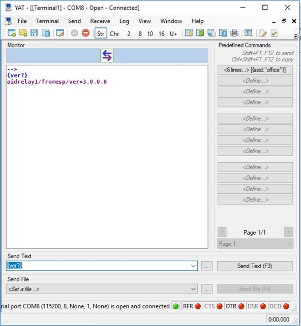
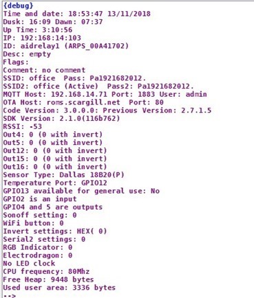
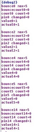
Having discovered some less than ideal historical settings in ESP-GO, today I’ve removed all commands which could OUTPUT to GPIO0. a throwback to the old ESP-01 days. I’ve also updated some default input bounce settings and improved the little-documented DEBUG2 command which lets you see the state of inputs on the serial terminal (I abandoned my own serial terminal some time ago in favour of the excellent and free YAT). The current software will be parked and esp-go-3 will appear, with GPIO 4 and 5 correctly used as boards with incorrect markings are by now likely out of circulation. While working on using SDK 3.1 (without success as the SDK appears to use more space than before) I’ve actually GAINED plenty of RAM to continue to expand with SDK 2.1 (which works a treat).
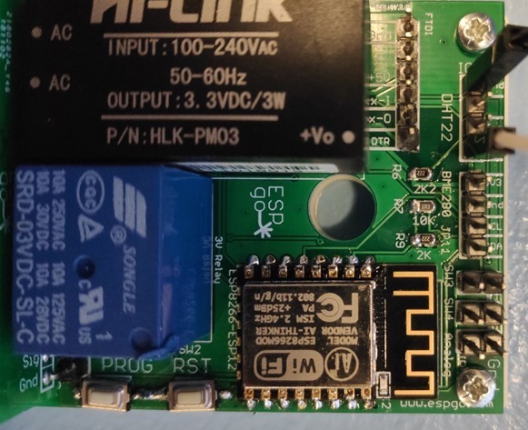
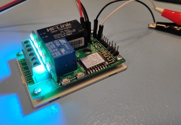
 Coincidentally, Aidan’s new boards are already into revision 2 to cater for the changes and to make some clearance improvements. Here are some pics. The board will be “revision 2” but this one will serve the purpose of demo.
We had these 2-sided boards made from Aidan’s design and Gerbers at JLCPCB and I must say the price and quality were just right.
The things to note about this board: mains power supply is included – note the connector at the bottom of the image above: The final board will differ slightly with N N L L SW SW in that order. Note the uncommitted contacts and the optional break-off LED board, used to provide a pretty display in the box and using one GPIO only (four WS2812b 5v LEDS).
The board is meant to go hand-in-hand with ESP-GO but of courses could be used with any software in the hands of a whiz as its brain is an ESP-12 board. The power supply provides easily enough 3v3 power to run the board and sensors like BME280 etc., the 3v3 relay and the internal LEDs. NOTE however that revision 2 is on the way – so there will be some delay before this goes any further -partly as Aidan wants to send off an order order comprising other designs as well and partly as I’m off on hols in the USA for 3 weeks (during which time I will be quietly working on ESP-GO-3 – shown working in the image below but not yet 100% tested – hey, I’m getting ready for my hols).
The current layout needs changes including a big capacitor as I noted a slight wiggle in the LED output, a pull-down for the input of the MOSFET driving the relay, greater earth clearances around pads and track clearance on the mains side. All of this has been added to the artwork and will go into the next set of boards which JLCPCB will hopefully produce and ship pronto. Thanks to readers for pointing out (almost to be expected)prototype issues.
I tend to use these 10 amp relays up to a maximum of 1KW (a tad over 4 amps on 220v mains) for inductive loads – so 4 amps AC or less (for inductive loads) makes sense. This applies also to the likes of Sonoff boards and similar with 10 amp relays. Of course track width and relay quality are also important. Anyone contemplating using this design may (or may not) care to consult the regulations in their country.
The board is a perfect fit for the smaller (and cheaper) of the two boxes described here – https://tech.scargill.net/box-nirvana/
Note the connections – GPIO4 and 5 are brought out with 3v3 I2c-compatible pull-ups. GPIO 2 and 14 are available as inputs for buttons (short to 0v for pressed).
Above, I’m testing the board serially… I use YAT.
The board will use GPIO15 to power the relay via a MOSFET and GPIO16 for indicator RGB LEDs (GPIO16 is no good as an input so unless you’re planning ultra-low power stuff it is as good a choice as any).
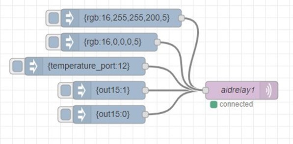
So GPIO16 on this board is powering the nifty WS2812b display LEDs from a single port. I can’t show you this at it’s best without video so you’ll have to accept that this is a fairly smooth fade with full RGB colour control, primarily to make the box look like it is doing something.. I am of course using Node-Red to control this (along with my house and other experiments on the same Raspberry Pi 3 that is also running PIHOLE and PIVPN without breaking a sweat).
A note for those who like to worry… no we’re not going into production. Aidan will likely make the Gerbers available and even provide boards at a reasonable price for interested parties. Under no circumstances do either of us accept any responsibility if you blow yourself up – be warned.
This stuff is meant for experienced experimenters and in this case involves working with dangerous mains wiring. Be warned. The power supply is of the insulated type but best to avoid touching anything when mains is connected. When programming I use an FTDI, but as this board runs on 3v3 and FTDI 3v3 output is often low, I use a 3v3 supply to provide power to the board when testing, not mains – I value my hands.
This is quite exciting. More capable than a Sonoff and uncommitted contacts, too.


Hi Pete
Just wondering how your getting on with PiHole, I’ve only recently discovered this as I was a firefox/ABP user. PiHole does some things better then ABP but not all, will be investigating blocking streaming adds once I sort out my moral conundrum.
Have also added get_iplayer to the PiHole device, as an alternative to setting the video recorder 😉
My phone bills having been rising due to the way I use the diversion services and I hope to look at RasPBX to act as a mobile gateway to divert offices calls to me as mobile to mobile will be more cost effective, just some thoughts and thanks for this blog.
Jason
Pihole just works as does pivpn so I don’t mess with it – sadly one of them is no longer supported, can’t remermber which – a real shame as the whole setup is just so easy.
it’s pivpn, but let’s hope someone creates something similar using wireguard instead of openvpn, a more modern vpn solution
edit: oh, they did! 🙂 https://github.com/whiskerz007/wireguard_rpi_installer
for a lot of info about wireguard, look this video by DrZzs… long as it was a live stream, but useful… and keep in mind that now most of that install is done by that script above 🙂 https://www.youtube.com/watch?v=Q6pR_JEMRQA
an other install script: https://github.com/l-n-s/wireguard-install
I’ve marked this one for future. Thanks for that… once I’m done with the stat I’ll take a look but will it cooperate with pihole?
Thinking about it – the only client referred to is UBUNTU PC. Need Windows 10 clients and Android phone clients. Router client would be the icing on the cake.
android client: https://play.google.com/store/apps/details?id=com.wireguard.android
windows client is coming soon, it’s the only one still missing: https://www.wireguard.com/install/
why not, they’re just 2 separate components… we’ll test it 🙂
Yes, I’ve modded the PCB and will be ordering some prototypes soon. I try to bunde 2 or 3 designs together ad the shipping is the mahor part of the cost.
I can post the design though as the only change that I’ve done is to move the LEDs to another port
Hi Aiden/Peter,
Not sure if I missed it but what’s the latest position on the ESP Go boards. I’m ready and waiting to order and finally get my wife of my back. She really does not like all these hand built sensors scattered all around the house.
My box order from Banggood should be arriving any day so I will have all the bits waiting and the boxes to put them in. Looking forward to tidying everything up with the new boards.
Thanks for all your efforts guys.
You didn’t miss anything – we switched IO bits as GPIO15 (I should have known better) has a pull-down which can prevent power-up output pulses on a relay – so we swapped ports around for rev 2 so that GPIO16 ends up powering the RGB LED indicators on the board. The RGB LED is not working for reasons even though GPIO16 is responding to 1 and 0 signals – currently beyond both of us and we’ve not had time to get to the bottom of it. Something for over the Christmas period slon with all the other things – and wives and friends etc.
Many thanks for the update Peter. I, and I suspect many others appreciate all the hard work you and Aiden are putting into this project. Keep up the great work.
Best of luck finding the bug, I’m presently struggling with intransigent Sonnof Basic switches running Tasmoto. After weeks of working well, my latest batch has started randomly corrupting. Hmm! The joys of electronics.
Hi Aiden/Pete, Any news/updates on the boards?
Michael
Yes, after remembered that of course GPIO16 has different timings to the rest and hence cannot be used with the same RGB code (and not wanting to write a special verion for GPIO16 as I had a hard enough time getting perfectly smooth RGB colour fading as it is) I’ve convinced Aidan to make a minor change to the artwork to use the pins slightly differently – this will have to fit into his next board schedule.
When we have a working board I’ll post it up here.
Thanks Peter. I now have all the box’s and various parts ready to build the initial 15 units I want to build to control my heating, alarms and sensors and replace the many hand built temporary electronics hanging off walls.
Keep up the good work.
Michael.
Don’t count on the bare boards any time soon. It is all down to when Aidan can fit them in.
A very desirable board, have the gerber files been made available yet?
Aidan, Elektor is still around and I have subscribed to it this year. I won’t re-subscribe as it is somewhat expensive and the majority of the content doesn’t interest me. As I am mainly into Arduino’s and ESP’s I get most of the information I need from Peter’s blog
Yes, you can never cover every base
Is there a freewheeling diode across the relay for switching such an inductive load?
Do you mean across the relay coil? If so, then yes of course! We’d get regular crashes when switching if not
There’s nothing across the relay contacts as we have no idea what loads people will switch. On a previous board, I put a 400VDR to absorb any arcing from inductive loads to prolong relay contact life, but discovered that the very small capacitance of a VDR can sometimes hold certain types boiler running at times.
In other words, if you have a load such as a heating boiler that has a digital input rather than a switched mains input (like Petes old heating boiler in fact!), then when you switch the boiler on, sometimes it will keep on running even when the relay has opened.
For this reason, we stopped fitting VDRs to our designs. If you use an inductive load, just put a VDR into the 0.2″ connector with the load wires.
OK, thank you for confirming this point!
On the relay contact, there is nothing you can do that will work for everything.
And yes, the best you can do is to provide a footprint and/or a screw terminal so it is easy to fit a VDR if required, with a big warning side for this problem!
Preferably two (diodes). You don’t get just positive spikes.
No, you are confusing VDR (Voltage Dependent Resistors) with TVS (Transcient Voltage Suppressors): the first one is a resistor and thus not polarized, whereas the second is a diode, although you can find bidirectional TVS
Nope, I was talking about diodes still, not the contact side of the relay.
Sorry, but the blog always moved my comment down, out of sequence, which is what the “(diodes)” comment was meant to clarify.
-John-
Then I don’t understand: this flyback diode is meant to prevent the inductive voltage pulse on turnoff, and you only get a spike when discharging, as this is when you have energy to sink.
Thus a single diode across the relay solenoid with its cathode connected to the positive supply is enough:
https://en.wikipedia.org/wiki/Flyback_diode
I remember that! Of course an even lower current way is to use a latching relay, but they’re not as cheap as a Chinese Songle relay
For a couple of years, not long ago, I subscribed to Elektor but I haven’t seen it for a while. It may be that tech blogs(!) are taking over the role of magazines?
Here in Australia we have an excellent monthly magazine, Diyode. Available in print or online (as they all are these days). See https://diyodemag.com/
We also have another excellent monthly magazine, Silicon Chip. See https://www.siliconchip.com.au/
So, yes, still around!
You are using 5v LEDs from a 3v3 supply. I have little experience of these but the devices I have say 3.7v minimum. They obviously seem to work though…
The serial LEDs definitely work on 3v3, no problem.
Lower voltages are usually OK (albeit dimmer) until you get close to the forward voltage drop. This will be fine for the reds but for the green elements this limit is typically in the range of 3.0 to 3.2V and blue elements 3.2 to 3.4V .
Not far off – remember these are not just LEDs, they are LEDs with a control chip on each one – for PWM control. Possibly there is some kind of switcher in there.
Right now I’m running the lot off my desk “precision” power supply and had not noticed I have the voltage set incorrectly. I’ve been running the lot all day on test at 3v with all five LEDs full on ie WHITE. JUST under that voltage the colour temperature is affected visibly.
At 3v3 the LEDs are a little brighter, that’s all. I’ve now adjusted the supply to 3v3 and the Hi-Link supply will put out 3v3 at 1 amp – the ESP12 is taking a tiny fraction of that (with WIFI peaks at maybe 300ma). Off the top of my head I’ve no idea what the relay needs, Aidan may interject…
From memory, the relay needs around 40mA. I’ve experimented with putting a series resistor and a capacitor into the power line of the relay with some success. This means thatt the realy gets a pulse of full voltage which pulls it in, then a reduced voltage/current to hold it.
You can more-or-less half the holding current using this method, but we have no need for that on the new board
That takes me back. 🙂 The recommended method used to be something like a BC108 with an emitter resistor sized for minimum, reliable holding current plus a 220uf slapped across it (and with the relay coil between +ve and the collector, of course). Do they still have anything like Everyday Electronics or ETI nowadays?
-John-
I tend to go for 1mm (or thinner) PCBs. They ‘snap’ on scribe lines which is a little neater than Aidan’s perforations.
Also, you could possibly ‘panellize’ your PCBs? I can’t tell your dimensions but if you can fit two on the 100×50 JLCPCB template you get 20 boards instead of 10 🙂
I’l get Aidan to answer that one Ian – good comment.
Meanwhile after all this time I continue to make discoveries – like GPIO16 going HIGH on reset (even with a temporarty pull down) – GPIO15 stays LOW… so no problem for revision 2 of the board, but WHY? And how did I miss that before?
Hi
I’ve panelised the PCBs as 2 up – you can use JLCPCBs 100×100 service to get 20 off. I didn’t go for scribed panelisation as they charge more for that. However, I’ve moved the break off holes a lot closer together. I can do a panelised version without the holes if you like, it won’t take long.
It’s a good point about thinner PCBs as they will indeed snap more easily and leave a teeny bit more height
FYI – I’ve ordered the new PCB for debugging – fingers crossed, I’ve got everything correct. If all goes well, I’ll get Pete to upload the zipped GERBERs next week.
This is turning out to be a great little board and I’ve already earned some brownie points with the wife as I’ve put one one her office tank and used Blynk to create a control app for her iPhone.
Now she can see the water temperature (using a stainless steel enclosed DS18B20 sensor), change the lighting colour and turn the pump on and off – all from a little box stuck onto the back of the tank. I’m really pleased that we decided to put a mains power supply on the board – one of those nice, safe looking enclosed ones – as it makes it much easier to deploy than using a USB supply